REVERSIBLE LOGIC SYNTHESIS
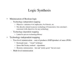
REVERSIBLE LOGIC SYNTHESIS. Overview of the Presentation. 1. Introduction. 2. Design of a Reversible Full-adder Circuit. Part 1. Introduction. What is Reversible Logic / Reversibility ?. The gate/circuit that does not loose information is called reversible.

REVERSIBLE LOGIC SYNTHESIS
E N D
Presentation Transcript
Overview of the Presentation 1. Introduction 2. Design of a Reversible Full-adder Circuit
Part 1 Introduction
What is Reversible Logic / Reversibility ? The gate/circuit that does not loose information is called reversible . Defn 1: A Reversible circuit has the facility to generate a unique output vector from each input vector, and vice versa . Input Vector Iv=( Ii,j , Ii+1,j , Ii+2,j , … , Ik-1,j, Ik,j ) Output Vector Ov=( Oi,j , Oi+1,j , Oi+2,j , … , Ok-1,j, Ok,j ) For each particular vector j IvOv
i O 1 1 i O 2 2 i O Reversible Gate 3 3 i O K-1 K-1 i O K K What is Reversible Logic / Reversibility ? (cont.) Defn 2: Reversible are circuits in which the number of inputs is equal to the number of outputs and there is one-to-one mapping between vectors of inputs and outputs. A gate with k inputs and k outputs is called k*k gate.
Difference Between Reversible Gate and Irreversible Gate Truth Table For Irreversible EXOR Logic
Difference Between Reversible Gate and Irreversible Gate (cont.) Truth Table For Reversible EXOR Logic (Feynman Gate)
Motivation Towards Reversible Gate It has been proved ( by Bennett and Landauer [1]) that , “losing information in a circuit causes losing power. Information lost when the input vector cannot be uniquely recovered from the output vector of a combinational circuit”. The gate/ circuit does not loose information is called reversible.
Garbage Bit Every gate output that is not used as input to other gate or as a primary output is called garbage. The unutilized outputs from a gate are called “garbage”. Heavy price is paid off for every garbage output. P = A * A B Q = A B
A P 0 1 A P = A' 1 0 Not Gate Some Popular Reversible Gates 1 x 1 Not Gate
Some Popular Reversible Gates (cont.) A B P Q 0 0 0 0 A P = A Feynman Gate 0 1 0 1 B Q = A B 1 0 1 1 1 1 1 0 2 x 2 Feynman Gate (CNOT Gate) [2]
Some Popular Reversible Gates (cont.) A B C P Q R 0 0 0 0 0 0 0 0 1 0 0 1 0 1 0 0 1 0 A P = A 0 1 1 0 1 1 Toffoli Gate B Q = B 1 0 0 1 0 0 C R = AB C 1 0 1 1 0 1 1 1 0 1 1 1 1 1 1 1 1 0 3 x 3 Toffoli Gate [3]
Some Popular Reversible Gates(cont.) A B C P Q R 0 0 0 0 0 0 0 0 1 0 0 1 0 1 0 0 1 0 A P = A 0 1 1 0 1 1 Fredkin Gate B Q = A'B AC 1 0 0 1 0 0 C R = A'C AB 1 0 1 1 1 0 1 1 0 1 0 1 1 1 1 1 1 1 3 x 3 Fredkin Gate [4]
Some Popular Reversible Gates(cont.) A B C P Q R 0 0 0 0 0 0 0 0 1 0 1 1 0 1 0 0 0 1 0 1 1 0 1 0 1 0 0 1 0 1 1 0 1 1 1 1 A P = A 1 1 0 1 1 0 New Gate B Q = AB C 1 1 1 1 0 0 C R = A'C' B' 3 x 3 New Gate (Khan Gate) [5]
Some Popular Reversible Gates(cont.) A B C P Q R 0 0 0 0 0 0 0 0 1 0 0 1 0 1 0 0 1 0 0 1 1 0 1 1 1 0 0 1 1 0 1 0 1 1 1 1 A P = A 1 1 0 1 0 1 Peres Gate B Q = A B 1 1 1 1 0 0 C R = AB C 3 x 3 Peres Gate[6]
Different Modes of Feynman Gate A as control input Output B as control input Output P Q P Q 0 0 B 0 A A 1 1 B' 1 A A' 0 P = 0 A P = A Feynman Gate Feynman Gate B Q = B 0 Q = A 1 P = 1 A P = A Feynman Gate Feynman Gate Q = B' B Q = A' 1 All possible cases in 2 x 2 Feynman Gate
Realizations of Irreversible Gates Using Reversible Gates A P = A Toffoli Gate B Q = B 0 R = AB 0 = AB A AND GATE C = AB B AND GATE
Realizations of Irreversible Gates Using Reversible Gates(cont.) A P = A Toffoli Gate B Q = B 1 R = AB 1 = AB A NAND GATE C = AB B NAND GATE
Realizations of Irreversible Gates Using Reversible Gates(cont.) A OR GATE C = A + B B A P = A Toffoli Gate B Q = B 1 R = A B 1 =A B =A + B OR GATE
Realizations of Irreversible Gates Using Reversible Gates(cont.) A NOR GATE C = A + B B A P = A Toffoli Gate B Q = B 0 R = A B 0 = A + B NOR GATE
The main rules for efficient reversible logic synthesis The main rules for efficient reversible logic synthesis Use as many outputs of every gate as possible, and thus minimize the garbage outputs. Do not create more constant inputs to gates that are absolutely necessary. Avoid leading output signals of gates to more than one input( Fanout). Don’t use any feedback loop; it is strictly restricted. Use as less number of reversible gates as possible to achieve the goal.
Part 2 Design of a Reversible Full-adder Circuit
Input Output A B Cin Sum Cout 0 0 0 0 0 0 0 1 1 0 0 1 0 1 0 0 1 1 0 1 1 0 0 1 0 1 0 1 0 1 1 1 0 0 1 1 1 1 1 1 Design of a Reversible Full-adder Circuit Sum=A B C Carry=AB + BC + CA =AB BC CA
Design of a Reversible Full-adder Circuit(cont.) A EXOR GATE A B EXOR GATE Sum B AND GATE EXOR GATE AND GATE C Carry AND GATE EXOR GATE Sum=A B C Carry=AB + BC + CA =AB BC CA
A P = A Feynman Gate B Q = A B P = A B Feynman Gate C Q = A B C = Sum Design of a Reversible Full-adder Circuit Sum=A B C Carry=AB + BC + CA =AB BC CA
A C B P = A P = B P = C Toffoli Gate Toffoli Gate Toffoli Gate A C B Q = A Q = B Q = C P = AB P = AB BC 0 0 0 R = BC R = AB R = CA Feynman Gate Feynman Gate Q = AB BC Q = AB BC CA= Carry Design of a Reversible Full-adder Circuit (cont.) Sum=A B C Carry =AB BC CA
A A Toffoli Gate B B P = A B 0 AB Feynman Gate Q = A B C = Sum Design of a Reversible Full-adder Circuit (cont.) A Feynman Gate A B A B Toffoli Gate C C (A C)B CA = Carry Sum=A B C Carry= =AB BC CA = (A C)B CA
Existing Reversible Full-adder Circuits Four Gates & Two Garbage outputs [7] Three Gates & Three Garbage outputs [5]
Proposed Reversible Full-adder Circuits Three Gates & Two Garbage outputs Two Gates & Two Garbage outputs
Input Section OutputSection A B Cin Sum (S) Cout 0 0 1 1 0 0 1 0 1 0 1 0 0 1 0 Theorem: A reversible full-adder circuit can be realized with at least two garbage outputs
Input Section Output Section A B Cin S Cout G1 0 0 1 1 0 0 0 1 0 1 0 0 1 0 0 1 0 1 A reversible full-adder circuit can be realized with at least two garbage outputs (cont.)
Input Section OutputSection A B Cin S Cout G1 G2 0 0 1 1 0 0 0 0 1 0 1 0 0 1 A reversible full-adder circuit can be realized with at least two garbage outputs (cont.)
References [1] C. H. Bennett. Logical reversibility of computation, IBM J. Research and Development, 17:pp. 525-532, November 1973. [2] R. Feynman, Quantum Mechanical Computers, Optical News (1985) 11-20. [3] T. Toffoli., Reversible Computing, Tech memo MIT/LCS/TM-151, MIT Lab for Computer Science (1980). [4] E. Fredkin, T Toffoli, Conservative Logic, International Journal of Theor. Physics, 21(1982), pp.219-253. [5] Md. M. H Azad Khan, Design of Full-adder with Reversible Gates, International Conference on Computer and Information Technology, Dhaka, Bangladesh, pp 515-519, 2002. [6] Peres, A., Reversible Logic and Quantum Computers, Physical Review A, 32: 3266-3276, 1985. [7] A. Mishchenko and M. Perkowski. Logic synthesis of reversible wave cascades. International Workshop on Logic Synthesis, pages 197-202, June 2002.
REVERSIBLE LOGIC SYNTHESIS The End