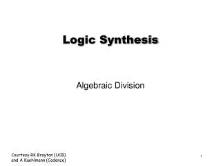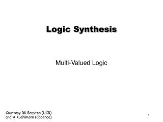
Dynamic Logic Synthesis
Dynamic Logic Synthesis. Basic Domino CMOS Gate. precharge transistor. inverting buffer. N logic. evaluate transistor. Clock . Constraint for Implementing Logic with Domino Gates. Inverter-free logic (Unate)

Dynamic Logic Synthesis
E N D
Presentation Transcript
Basic Domino CMOS Gate precharge transistor inverting buffer N logic evaluate transistor Clock
Constraint for Implementing Logic with Domino Gates • Inverter-free logic (Unate) • All logic inversions performed at inputs or outputs (where inverters can be absorbed in registers) • Pushing inverters from output toward input by DeMorgan’s laws
Trapped Inverters invi O2 • Non-reconvergent fan-out • Reconvergent fan-out : conei must be duplicated conei Ni O1 invi conei Ni O
Output Phase Assignment invi • Remove trapped inverter in non-reconvergent fan-out O2 conei Ni O1 O2 O2 : Negative Polarity conei Ni O1 : Positive Polarity O1
Conflicting Output Phase O3 O2 O1 Conflicting requirement for output O2
Computing the Polarity of Outputs forFan-out Net • From output to input • Initially, for each Oj : [ – – vj = P – – ] • Propagating AND/OR gate : • vector remains the same • Propagating NOT gate : • vector is complemented [ P ] [ P ] [ P ] [ N ] [ P ]
Computing the Polarity of Outputs for Fan-out Net [N P ] • Fan-out net : • combine vectors [N P N] [N N]
Example [ P] [ P] O3 [ P] [ P P] [ P ] [ P ] O2 [ N ] [ P ] [P N ] [P ] O1 [P ]
Trapped Inverter at Reconvergent Fan-out [ P N ] • Combine vector for one fan-out • Trapped inverter at re-convergent fan-out need duplication of fan-in cone of Net 1 Net1 [ N P ]
Trapped Inverter at Non-reconvergent Fan-out • After assignment for all fan-out Net • Net 1 : [ N P N ] • Net 2 : [ P P N ] • Conflicting requirement of Output 1 trapped inverter at non-reconvergent fan-out need duplicating fan-in cone of Net 1 or fan-in cone of Net 2
Model the Minimum Duplication Problem N1 : [ P P – ] N2 : [ N – P ] N3 : [ P – P ] N4 : [ – N P ] • Model the constraints as 2-SAT formula : (N1+N4) (N1+N2)(N2+N3) • If a variable evaluates true, its fan-in cone is duplicated. N1 N2 N4 N3
Removal of Trapped Inverter • Use technique of redundancy addition and removal • Make trapped inverter redundant by adding logic • Add logic close to output. If inverters are added, the added logic is implemented by CMOS logic