Download
1 / 26
260 likes | 661 Vues
Position Sensorless Control for For Four-Switch Three-Phase Brushless DC Motor Drives. Adviser : Cheng-Tsung Lin Student :N an-hui Hsieh. Outline. Abstract Introduction NOVEL PWM SCHEME FOR FSTP BLDC MOTOR SENSORLESS SCHEME Back EMF Waveform Novel Sensorless Control Scheme

E N D
Position Sensorless Control for For Four-SwitchThree-Phase Brushless DC Motor Drives Adviser : Cheng-Tsung Lin Student :Nan-huiHsieh
Outline • Abstract • Introduction • NOVEL PWM SCHEME FOR FSTP BLDC MOTOR • SENSORLESS SCHEME • Back EMF Waveform • Novel Sensorless Control Scheme • Starting Technique • Experiments Results • Conclusions • References
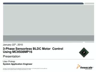
Abstract • This paper proposes a position sensorless controlscheme for four-switch three-phase (FSTP) brushless dc (BLDC)motor drives using a field programmable gate array (FPGA). • A novel sensorless control with six commutation modes and novel pulsewidth modulation scheme is developed to drive FSTP BLDC motors. • The low cost BLDC driver is achieved by the reduction of switch device count, cost down of control, and saving of hall sensors.。 • The feasibility of the proposed sensorless control for FSTPBLDC motor drives is demonstrated by analysis and experimental results. • In contrast, if six commutation modes presented in [5] is used in the four-switch inverter, then there are four floating phases during the operating period. Hence, the position information can be detected from the floating line.
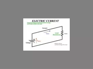
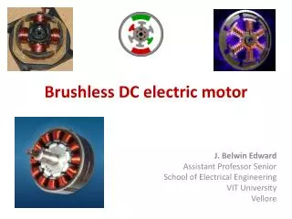
Introduction • For BLDC motors with a trapezoidal back EMF, rectangularstator currents are required to produce a constant electric torque[16].RECENTLY, the brushless dc (BLDC) motor is becomingpopular in various applications because of its high efficiency,high power factor, high torque, simple control, and lower maintenance.
Introduction • Three-phase voltage source inverters with only four switches, as shown in Fig. 2, is an attractive solution.
Introduction • In comparison with the usual three-phase voltage-sourceinverter with six switches • The main features of this converter aretwofold: 1.The first is the reduction of switches and freewheeling diode count. 2.The second is the reduction of conduction losses. • Almost all sensorless control schemes [7]–[11] for six-switchthree-phase BLDC motors have to detect the zero-crossing pointof voltage waveforms from unexcited windings to estimate therotor position • In contrast, if six commutation modes presented in [5] is used in the four-switch inverter, then there are four floating phases during the operating period. • Hence, the position information can be detected from the floating line. This paper presents a novel sensorless control scheme for the FSTP BLDC motors based on [5].
II. NOVEL PWM SCHEME FOR FSTP BLDC MOTOR DRIVES • The proposed voltage pulsewidth modulation (PWM)scheme for FSTP inverter requires six commutation modeswhich are (X,0), (1,0), (1,X), (X,1), (0,1) and (0,X), as shown inFig. 4.
II. NOVEL PWM SCHEME FOR FSTP BLDC MOTOR DRIVES • In Mode II, if the FSTP BLDC motor drive uses the conventional voltage PWM scheme as shown in Fig. 5, two stages corresponding to (1,0) and (X,0) in Mode II, respectively, are shown in Fig. 6(a) and (b).
II. NOVEL PWM SCHEME FOR FSTP BLDC MOTOR DRIVES • This conventional voltage PWM scheme provides a discharging loop between the capacitor and the low-side switch, and causes non-rectangular stator current waveforms which are harmful for constant torque, as shown in Fig. 6(c).
II. NOVEL PWM SCHEME FOR FSTP BLDC MOTOR DRIVES • This paper proposes a novel voltage PWM to overcome this drawback, as shown in Fig. 7.
II. NOVEL PWM SCHEME FOR FSTP BLDC MOTOR DRIVES • There are three stages corresponding to (1,0), (X,0), and (X,X), respectively, in Mode II for the novel voltage PWM scheme, as shown in Fig. 8(a)–(c). • Experimental results show that the stator current waveforms of the FSTP inverter using this novel voltage PWM scheme is rectangular, as shown in Fig. 8(d). Similar situations apply to Mode V.
II. NOVEL PWM SCHEME FOR FSTP BLDC MOTOR DRIVES • The new stage (X, X) of this novel PWM scheme in Modes IIand V is introduced to turn off all power devices to prevent thecapacitor discharging from the low-side switch. • Further more, the supply voltages in Modes II and V are double of those in the other four Modes while the PWM duty cycles in Modes I, III, IV and VI are double of those in the Mode II and V. • We call this novel voltage PWM scheme as the asymmetric PWM scheme for FSTP BLDC motor drives. The commutation sequence and the PWM duty are shown in Table I.
SENSORLESS SCHEMEA. Back EMF Waveform • The FSTP BLDC motor drives using the novel voltage PWMscheme have two phases to detect the back EMF, but the splitcapacitors cause the voltage waveform of back EMF to btriangular like. • The voltages detected from phases A and B become two triangular like waveforms, and the voltage of the uncontrolled phase (phase C) becomes Vdc/2, as shown in Fig. 9.
SENSORLESS SCHEMEA. Back EMF Waveform • Furthermore, the stator current waveform of the floating phaseis rectangular • Thus, it is impossible to detect the freewheel diode conducting current by the conventional zero-crossing method. • Therefore, the conventional sensorless methods for BLDC motors using six-switch three-phase inverter could not be directly used in the FSTP BLDC motors. • Fortunately, after observing a lot of experimental results, wefound that there we two waveform crossings between phase Aand B voltagewaveforms which can be used to estimate the rotorposition.
SENSORLESS SCHEME B. Novel Sensorless Control Scheme • If we install rotor position sensors (Hall sensors) into BLDCmotors, when we observed the voltage waveforms of phases Aand B, we found that two waveform crossings matched the two Hall signals (101 and 010) at the same time, respectively, asshown in Fig. 9. • Therefore, we propose to use the two crossings for rotor position estimation for sensorless commutation purposes.
SENSORLESS SCHEME B. Novel Sensorless Control Scheme • We detect the first crossing (P1) and set the crossingtiming counter to be 0. When we detect the second crossing (P2)and if the crossing timing counter is N, then the time difference,T, between two crossings can be estimated, and we reset timecounter to zero. • Because there are two commutations (e.g., Mode V andMode VI) between two crossings (P1 and P2), we can estimate the timing of the two commutations, TC1and TC2 , as follows • In constant speed operation, since the time difference of everycommutation is constant, the first estimated commutation(TC1)is equal to T/3, and the second estimated commutation TC2 is 2T /3.
SENSORLESS SCHEME B. Novel Sensorless Control Scheme • Because there are only four crossings in one revolution, the rotor speed,W , is equal
IV. EXPERIMENT RESULTS • The first step to start the sensorless drive is to get the initialrotor position. • Since only in Modes II and V the BLDC motor is supplied by whole dc bus, the inverter could supply enough power to drive the rotor to an expected position. • Therefore, for starting we simply excite the motor in Modes II or Mode V to force rotor to rotate in the specified direction. • Therefore, we propose to use the two crossings for rotor position estimation for sensorless commutation purposes.
EXPERIMENT RESULTS A. Experimental Setup • The motor used in the experimental set-up is produced byTroy in Taiwan, and its parameters are shown in Table II. Thecrossings of the two controlled voltages which are filteredby low pass filters (LPF), are detected by a comparator. • The split capacitor bank must be large enough that it can be treated as a voltage source. • The voltage across capacitors and the voltage ripple areapplied across the switch. It is reasonable to allow 5% voltage ripple in the voltages across C1 and C2 [17], [18]. The relationship between the capacitors’ ripple voltage and the current in the capacitors is • Therefore, we propose to use the two crossings for rotor position estimation for sensorless commutation purposes.
IV. EXPERIMENT RESULTS A. Experimental Setup • The rated current is 1 A, the carrier is 4 kHz and the supplyvoltage is 320 V, so the capacitor must be larger than • We used two 330 uF capacitors in our experiment, becausethe capacitors had to supply startup current. • Therefore, we propose to use the two crossings for rotor position estimation for sensorless commutation purposes.
IV. EXPERIMENT RESULTS B. Experiment Results • The detailed schematic diagram of the sensorless controlshown in Fig. 11 consists of four blocks: startup procedure,sensorless_module, speed_calulator, and asymmetric PWMgenerator. • Therefore, we propose to use the two crossings for rotor position estimation for sensorless commutation purposes.
IV. EXPERIMENT RESULTS B. Experiment Results • The detailed schematic diagram of the sensorless controlshown in Fig. 11 consists of four blocks: startup procedure,sensorless_module, speed_calulator, and asymmetric PWMgenerator. • Therefore, we propose to use the two crossings for rotor position estimation for sensorless commutation purposes.
IV. EXPERIMENT RESULTS B. Experiment Results • In the sensorless_module, we use one XOR logic circuit toproduce triggers for the rising and falling edges of the comparator. • The trigger will enable the latch to catch the time intervalfrom the timing counter, and then reset the timing counter.TC1 is equal to the timing interval multiplied by 1/3 (Q161/3= 65535/3= 21845 , TC2 and is double of TC1. Thedetailed circuit is shown in Fig.12and the timing simulationin Fig. 13. • Therefore, we propose to use the two crossings for rotor position estimation for sensorless commutation purposes.
IV. EXPERIMENT RESULTS B. Experiment Results • In Fig. 13, the “comp” is the input signal from thecomparator, the “xor_comp” the trigger for the latch and timingcounter, “count” the time interval between two crossings, and“hall_sless” the estimated communication mode. • From the results of timing simulation, we can observe that the latch grabs time interval when xor_comp rises, and the operating time of the two estimated commutation modes is equal to the third of the time interval. • The speed response of the FPGA-based sensorless control forFSTP BLDC motor drives is shown in Fig. 14. From the figure we can observe that the rotor speed is accelerated to the specified speed (720 rpm) because the novel sensorless scheme can estimate the correct rotor position. • Therefore, we propose to use the two crossings for rotor position estimation for sensorless commutation purposes.
V. CONCLUSION • This paper has presented a novel FPGA-based sensorlesscontrol scheme for four-switch three-phase brushless dc motordrives. In the scheme, a novel asymmetric PWM scheme usingsix commutation modes in the FSTP inverter is proposed. • The position information is estimated from the crossings of voltage waveforms in floating phases, and a low cost FPGA is utilized to implement the algorithm. • Because the stator current waveforms of the FSTP inverter using this novel voltage PWM scheme are rectangular, the motor will operate smoothly and the torque ripple will be at the same level as reported in [5]. • However, the two estimated commutations maybe cause commutation torque ripple. The experimental results show that the scheme works very well. With the developed control scheme and the lowest cost implementation, the proposed scheme is suitable for commercial applications. • Therefore, we propose to use the two crossings for rotor position estimation for sensorless commutation purposes.