Download
1 / 29
1.11k likes | 2.9k Vues
Modeling and Speed Control of Brushless DC Motor Drives by Load Torque Estimation. By ANJU K P. Edited By Sarath S Nair www.technologyfuturae.com. OVERVIEW. Introduction BLDC Advantages, disadvantages and applications of BLDC Modeling of BLDC and current control method

E N D
Modeling and Speed Control of Brushless DC Motor Drivesby Load Torque Estimation By ANJU K P www.technologyfuturae.com Edited By Sarath S Nair www.technologyfuturae.com
OVERVIEW • Introduction • BLDC • Advantages, disadvantages and applications of BLDC • Modeling of BLDC and current control method • Conclusions • References www.technologyfuturae.com
INTRODUCTION • DC motors have many attractive properties such as high efficiency and linear torque speed characteristics . • The control of dc motors is simple and their hardware is less. • The main drawback of dc motor is the need of periodic maintenance • Thus DC motors have been gradually replaced by the BLDC www.technologyfuturae.com
The PI controller is usually employed in a BLDC motor control, which is simple in realization. But it is difficult to obtain the sufficiently high-performance applications. • Used a feedforward compensation method through load torque estimation • The estimated load disturbance by the state observer is compensated as the equivalent current • The d-q transform of phase currents were possible by the Fourier series summation method • This current control method was used to get compensation current of BLDC motor. www.technologyfuturae.com
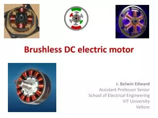
bldc • Permanent magnet synchronous motor, having permanent magnets on the rotor and trapezoidal shape back EMF. • The BLDC motor employs a dc power supply switched to the stator phase windings of the motor by power devices, the switching sequence being determined from the rotor position. • BLDC is driven by a three-phase inverter with, six-step commutation • Commutation timing is determined by the rotor position, which can be detected by Hall sensors www.technologyfuturae.com
Advantages, disadvantages and applications of BLDC ADVANTAGES • More Efficient • Less electrical energy is wasted • Reduced Noise • Longer Lifetime • Reduced EM Interference. • Torque, Voltage, And RPM Linearly Related DISADVANTAGES • High cost • More complex controller www.technologyfuturae.com
APPLICATIONS • They are having different power ratings from very small motors as used in hard disks to larger motors in electric vehicles • hard drives, CD/DVD players, and PC cooling fans use BLDC motors. • High power BLDC motors are found in electric vehicles and some industrial machinery. • A number of electric bicycles use BLDC motors • Certain HVAC systems, especially those featuring variable-speed and/or load modulation, use ECM motors . www.technologyfuturae.com
MODELING OF THE BLDC MOTOR AND CURRENT CONTROL METHOD www.technologyfuturae.com
Modeling ofBLDC Motor • The BLDC motor is an AC synchronous motor • The BLDC motor has three stator windings and permanent magnets on the rotor. • The modeling is based on the following assumptions: (1) The motor is not saturated. (2) Stator resistances of all windings are equal and self and mutual inductances are constant. (3) Power semiconductor devices in the inverter are ideal. (4) Iron Losses are negligible. www.technologyfuturae.com
Block diagram of BLDC motor drive www.technologyfuturae.com
Under the above assumptions, a BLDC motor can be represented as where ia, ib , and ic are rectangular shaped phase currents and ea, eb and ec are trapezoidal shaped back-EMFs. The electromagnetic torque is expressed as www.technologyfuturae.com where, wm is mechanical speed
Current Control Method • Input current reference value was calculated from the summation method of the Fourier series. • Phase current is rectangular shape and then, it's Fourier series is expressed as www.technologyfuturae.com Where a0=0 and an=0, because it is odd function
using above eqnd-q transform of phase current can be done • the electromagnetic torque is rewritten as www.technologyfuturae.com α is proportional constant for feedforward compensation, λm is linkage flux of permanent magnet, and iq is q axis stator current
The interaction of T, with the mechanical dynamics www.technologyfuturae.com where TLis the load torque, J is the inertia, w is the rotor speed, and B is the viscous damping.
Block diagram of proposed control algorithm BLDCM www.technologyfuturae.com
LOAD TORQUEOBSERVER • The proposed speed control method requires information of the load torque for feedforward compensation. • Adirect measurement of the load torque is difficult because other high cost equipment is required. • Therefore, we use state observer to estimate value. Input value of the state observer is position information of rotor. • The system equations of a motor can be described as www.technologyfuturae.com where y is the rotor position
The dynamic equation of the given system can be expressed as www.technologyfuturae.com
A state observer for the load torque estimation can be represented as follows www.technologyfuturae.com
Estimated state vector can be represented as www.technologyfuturae.com is the proportional gain vector to be chosen so as to determine the error dynamics of the observer
Estimated outputs of the observer are rotor position, speed,and load torque. • Estimated load torque is used for feedforward compensation • Reference current iq* is compensated as iq,com by estimated • motor speed quickly converges the reference shortly after startup and recovers very well from the load torque disturbance as well as parameters variation www.technologyfuturae.com
CONCLUSIONS • Though BLDC is costly and its control circuit is complex, it replaces DC motors in many applications due to its wide advantages . The basics of BLDC was discussed. • The feedforward compensation control improves the overall speed control performance in low speed controller gain. This technique was also discussed. • It is regarded as the best control method to get fast and accurate speed response. www.technologyfuturae.com
ReferenceS [1]Ki-Hong Park, Tae-Sung Kim, Sung-Chan Ahn, Dong-SeokHyun,”Speed Control of High-PerformanceBrushless DC Motor Drives by Load Torque Estimation”. [2]K. Ohishi, M. Nakao, K. Ohnishi and K. Miyachi,“Microprocessor-Controlled DC Motor for Load-Insensitive Position Servo System,” IEEE Trans. Ind. Electron., vol. 34, no. 1, pp. 44-49,1987. [3]Jong Sun KO, Jung Hoon Lee, Se Kyo Chung, and MyungJoongYoun,“A Robust Digital Position Control of Brushless DC motor with Dead Beat Load Torque Observer,” IEEE Trans. Ind. Electron., vol. 40, no. 5,pp. 512-520, May 1993. www.technologyfuturae.com
[4]P.Pillay and R. Krishnan, “Application Characteristics of Permanent Magnet Synchronous and Brushless dc Motors for Servo Drives,” IEEE Trans. Ind. Appl., vol. 27, no.5, pp. 986-996 Sept./Oct. 1991. [5]Guchuan Zhu, Dessaint, L.-A., Akhrif, O., and Kaddouri, A., “Speedtracking control of a permanent-magnet synchronous motor with state and load torque observer,” IEEE Trans, vol. 47, no. 2, pp. 346-355, Apr.2000. [6]StefánBaldursson,”BLDC Motor Modelling and Control – A Matlab®/Simulink®Implementation” Master Thesis work , Institutionen för Energi och Miljö International masters program in Electric Power Engineering , ChalmerstekniskaHogskolaGöteborg, Sverige, 2005 www.technologyfuturae.com
Technical Presentations, Research Reviews, New designs & Developments Log On to www.technologyfuturae.com TechnologyFuturae
THANK YOU… www.technologyfuturae.com