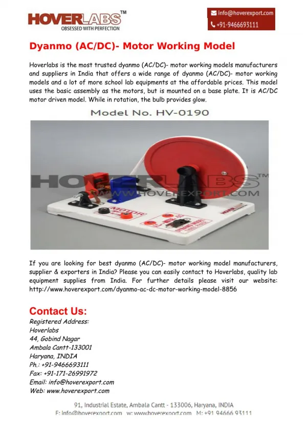
DC and AC Motor Drives
750 likes | 1.84k Vues
DC and AC Motor Drives. Introduction: DC Motor Drives. Direct current (dc) motors have variable characteristics and are used extensively in variable-speed drives. DC motors can provide a high starting torque and it is also possible to obtain speed control over a wide range.

DC and AC Motor Drives
E N D
Presentation Transcript
Introduction: DC Motor Drives • Direct current (dc) motors have variable characteristics and are used extensively in variable-speed drives. • DC motors can provide a high starting torque and it is also possible to obtain speed control over a wide range. • The methods of speed control are normally simpler and less expensive than those of AC drives. • DC motors play a significant role in modern industrial drives. • Both series and separately excited DC motors are normally used in variable-speed drives, but series motors are traditionally employed for traction applications. • Due to commutators, DC motors are not suitable for very high speed applications and require more maintenance than do AC motors. • With the recent advancements in power conversions, control techniques, and microcomputers, the ac motor drives are becoming increasingly competitive with DC motor drives. • Although the future trend is toward AC drives, DC drives are currently used in many industries. It might be a few decades before the DC drives are completely replaced by AC drives.
Introduction: DC Motor Drives • Controlled rectifiers provide a variable dc output voltage from a fixed ac voltage, whereas a dc-dc converter can provide a variable dc voltage from a fixed dc voltage. • Due to their ability to supply a continuously variable dc voltage, controlled rectifiers and dc-dc converters made a revolution in modern industrial control equipment and variable-speed drives, with power levels ranging from fractional horsepower to several megawatts. • Controlled rectifiers are generally used for the speed control of dc motors. • The alternative form would be a diode rectifier followed by dc-dc converter. • DC drives can be classified, in general, into three types: • 1. Single-phase drives • 2. Three-phase drives • 3. DC-DC converter drives
Basic Characteristics of Shunt DC Motors • The motor speed can be varied by • controlling the armature voltage Va, known as voltage control; • controlling the field current If, known as field control; or • torque demand, which corresponds to an armature current Ia, for a fixed field current If. • The speed, which corresponds to the rated armature voltage, rated field current and rated armature current, is known as the rated (or base) speed.
Basic Characteristics of Shunt DC Motors • In practice, for a speed less than the base speed, the armature current and field currents are maintained constant to meet the torque demand, and the armature voltage Va is varied to control the speed. • For speed higher than the base speed, the armature voltage is maintained at the rated value and the field current is varied to control the speed. • However, the power developed by the motor (= torque X speed) remains constant. • Figure below shows the characteristics of torque, power, armature current, and field current against the speed.
Basic Characteristics of Series DC Motors • The motor speed can be varied by • controlling the armature voltage Va, known as voltage control; • armature current Ia, which is a measure of the torque demand. • A series motor can provide a high torque, especially at starting; and for this reason, series motors are commonly used in traction applications.
Basic Characteristics of Series DC Motors • For a speed up to the base speed, the armature voltage is varied and the torque is maintained constant. • Once the rated armature voltage is applied, the speed-torque relationship follows the natural characteristic of the motor and the power (= torque X speed) remains constant. • As the torque demand is reduced, the speed increases. • At a very light load, the speed could be very high and it is not advisable to run a dc series motor without a load.
Operating Modes • In variable-speed applications, a dc motor may be operating in one or more modes: • motoring, • regenerative braking, • dynamic braking, • plugging, and • four quadrants. • Motoring: The arrangements for motoring are shown in Figure 15.7a. Back emf Eg is less than supply voltage Vy. Both armature and field currents are positive. The motor develops torque to meet the load demand.
Operating Modes • Regenerative braking: • The arrangements for regenerative braking are shown in Figure 15.7b. • The motor acts as a generator and develops an induced voltage Eg. Eg must be greater than supply voltage Va. • The armature current is negative, but the field current is positive. • The kinetic energy of the motor is returned to the supply. • A series motor is usually connected as a self-excited generator. • For self-excitation, it is necessary that the field current aids the residual flux. This is normally accomplished by reversing the armature terminals or the field terminals.
Operating Modes • Dynamic braking: • The arrangements shown in Figure 15.7c are similar to those of regenerative braking, except the supply voltage Va is replaced by a braking resistance Rb,. • The kinetic energy of the motor is dissipated in Rb.
Operating Modes • Plugging: • Plugging is a type of braking. The connections for plugging are shown in Figure 15.7d. • The armature terminals are reversed while running. The supply voltage Va and the induced voltage Eg act in the same direction. • The armature current is reversed, thereby producing a braking torque. The field current is positive. • For a series motor, either the armature terminals or field terminals should be reversed, but not both.
Operating Modes • Four Quadrants: • Figure 15.8 shows the polarities of the supply voltage Va, back emf Eg, and armature current Ia for a separately excited motor. • In forward motoring (quadrant I), Va, Eg, and Ia are all positive. The torque and speed are also positive in this quadrant. • During forward braking (quadrant II), the motor runs in the forward direction and the induced emf Eg continues to be positive. For the torque to be negative and the direction of energy flow to reverse, the armature current must be negative. The supply voltage Va should be kept less than Eg. • In reverse motoring (quadrant III), Va, Eg, and Ia are all negative. The torque and speed are also negative in this quadrant. To keep the torque negative and the energy flow from the source to the motor, the back emf Eg must satisfy the condition | Va | > | Eg|. The polarity of Eg can be reversed by changing the direction of field current or by reversing the armature terminals. • During reverse braking (quadrant IV), the motor runs in the reverse direction. Va, and Eg continue to be negative. For the torque to be positive and the energy to flow from the motor to the source, the armature current must be positive. The induced emf Eg must satisfy the condition | Va | < | Eg|.
Operating Modes • Four Quadrants: • Figure 15.8 shows the polarities of the supply voltage Va, back emf Eg, and armature current Ia for a separately excited motor.
Single-Phase Drives • If the armature circuit of a dc motor is connected to the output of a single-phase controlled rectifier, the armature voltage can be varied by varying the delay angle of the converter aa. • The basic circuit agreement for a single-phase converter-fed separately excited motor is shown in Figure 15.9. • At a low delay angle, the armature current may be discontinuous, and this would increase the losses in the motor. • A smoothing inductor, Lm, is normally connected in series with the armature circuit to reduce the ripple current to an acceptable magnitude. • A converter is also applied in the field circuit to control the field current by varying the delay angle af.
Single-Phase Drives • Depending on the type of single-phase converters, • single-phase drives may be subdivided into: • Single-phase half-wave-converter drives. • Single-phase semi converter drives. • Single-phase full-converter drives. • Single-phase dual-converter drives.
Single-Phase Half-Wave-Converter Drives • A single-phase half-wave converter feeds a dc motor, as shown below. • The armature current is normally discontinuous unless a very large inductor is connected in the armature circuit. • A freewheeling diode is always required for a dc motor load and it is a one-quadrant drive. • The applications of this drive are limited to the 0.5 kW power level. • Figure shows the waveforms for a highly inductive load. • A half-wave converter in the field circuit would increase the magnetic losses of the motor due to a high ripple content on the field excitation current.
Single-Phase Full-Wave-Converter Drives • The armature voltage is varied by a single-phase full-wave converter, as shown in Figure 15.13a. • It is a two-quadrant drive, as shown in Figure 15.13b, and is limited to applications up to 15 kW. • The armature converter gives + Va or - Va, and allows operation in the first and fourth quadrants. • During regeneration for reversing the direction of power flow, the back emf of the motor can be reversed by reversing the field excitation.
Single-Phase Full-Wave-Converter Drives • The converter in the field circuit could be a full, or even a dual converter. • The reversal of the armature or field allows operation in the second and third quadrants. • The current waveforms for a highly inductive load are shown in Figure 15.13c for powering action.
Single-Phase Full-Wave-Converter Drives • The converter in the field circuit could be a full, or even a dual converter. • The reversal of the armature or field allows operation in the second and third quadrants. • The current waveforms for a highly inductive load are shown in Figure 15.13c for powering action.
Single-Phase Dual-Converter Drives • Two single-phase full-wave converters are connected. • Either converter 1 operates to supply a positive armature voltage, Va, or converter 2 operates to supply a negative armature voltage, - Va. • Converter 1 provides operation in the first and fourth quadrants, and converter 2, in the second and third quadrants. • It is a four-quadrant drive and permits four modes of operation: forward powering, forward braking (regeneration), reverse powering, and reverse braking (regeneration). • It is limited to applications up to 15 kW. The field converter could be a full-wave or a dual converter.
Three-Phase Drives • The armature circuit is connected to the output of a three-phase controlled rectifier. • Three-phase drives are used for high-power applications up to megawatt power levels. • The ripple frequency of the armature voltage is higher than that of single-phase drives and it requires less inductance in the armature circuit to reduce the armature ripple current. • The armature current is mostly continuous, and therefore the motor performance is better compared with that of single-phase drives. • Similar to the single-phase drives, three-phase drives may also be subdivided into: • Three-phase half-wave-converter drives. • Three-phase semiconverter drives. • Three-phase full-converter drives. • Three-phase dual-converter drives.
Three-Phase Full-Wave-Converter Drives • A three-phase full-wave-converter drive is a two-quadrant drive without any field reversal, and is limited to applications up to 1500 kW. • During regeneration for reversing the direction of power • However, the back emf of the motor is reversed by reversing the field excitation. • The converter in the field circuit should be a single- or three-phase full converter.
Three-Phase Dual-Converter Drives • Two three-phase full-wave converters are connected in an arrangement similar to Figure 15.15a. • Either converter 1 operates to supply a positive armature voltage, Va or converter 2 operates to supply a negative armature voltage, -Va. • It is a four-quadrant drive and is limited to applications up to 1500 kW. • The field converter can be a full-wave converter. • If converter 1 operates with a delay angle of
Closed-Loop Control of DC Drives • The speed of dc motors changes with the load torque. • To maintain a constant speed, the armature (and or field) voltage should be varied continuously by varying the delay angle of ac-dc converters or duty cycle of dc-dc converters. • In practical drive systems it is required to operate the drive at a constant torque or constant power; in addition, controlled acceleration and deceleration are required. • Most industrial drives operate as closed-loop feedback systems. • A closed-loop control system has the advantages of improved accuracy, fast dynamic response, and reduced effects of load disturbances and system nonlinearities.
Closed-Loop Control of DC Drives • The block diagram of a closed-loop converter-fed separately excited dc drive is shown in Figure 15.25. • If the speed of the motor decreases due to the application of additional load torque, the speed error Ve increases. • The speed controller responses with an increased control signal Vc, change the delay angle or duty cycle of the converter, and increase the armature voltage of the motor. • An increased armature voltage develops more torque to restore the motor speed to the original value. • The drive normally passes through a transient period until the developed torque is equal to the load torque.
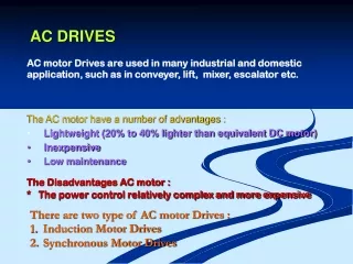
Introduction: AC Motor Drives • Ac motors exhibit highly coupled, nonlinear, and multivariable structures as opposed to much simpler decoupled structures of separately excited dc motors. • The control of ac drives generally requires complex control algorithms that can be performed by microprocessors or microcomputers along with fast-switching power converters. • The ac motors have a number of advantages; they are lightweight (20 to 40% lighter than equivalent dc motors), are inexpensive, and have low maintenance compared with dc motors. • They require control of frequency, voltage, and current for variable-speed applications. • The power converters, inverters, and ac voltage controllers can control the frequency, voltage, or current to meet the drive requirements.
Introduction: AC Motor Drives • These power controllers, which are relatively complex and more expensive, require advanced feed-back control techniques such as model reference, adaptive control, sliding mode control, and field-oriented control. • However, the advantages of ac drives outweigh the disadvantages. There are two types of ac drives: • Induction motor drives • Synchronous motor drives • Ac drives are replacing dc drives and are used in many industrial and domestic applications.
Induction Motor Drives • The speed and torque of induction motors can be controlled by • Stator voltage control • Rotor voltage control • Frequency control • Stator voltage and frequency control • Stator current control • To meet the torque-speed duty cycle of a drive, the voltage, current, and frequency control are normally used.
Induction Motor Drives: Stator Voltage Control • The stator voltage can be varied by three-phase • ac voltage controllers, • voltage-fed variable de-link inverters, or • pulse-width modulation (PWM) inverters. • However, due to limited speed range requirements, the ac voltage controllers are normally used to provide the voltage control. • The ac voltage controllers are very simple. • However, the harmonic contents are high and the input PF of the controllers is low. • They are used mainly in low-power applications, such as fans, blowers, and centrifugal pumps, where the starting torque is low. • They are also used for starting high-power induction motors to limit the in-rush current.
Induction Motor Drives: Rotor Voltage Control • In a wound-rotor motor, an external three-phase resistor may be connected to its slip rings, as shown in Figure 16.5a. • The developed torque may be varied by varying the resistance Rx. If Rx is referred to the stator winding and added to Rr, Eq. (16.18) may be applied to determine the developed torque. • The typical torque-speed characteristics for variations in rotor resistance are shown in Figure 16.5b.
Induction Motor Drives: Rotor Voltage Control • This method increases the starting torque while limiting the starting current. • However, this is an inefficient method and there would be imbalances in voltages and currents if the resistances in the rotor circuit are not equal. • A wound-rotor induction motor is designed to have a low-rotor resistance so that the running efficiency is high and the full-load slip is low. • The increase in the rotor resistance does not affect the value of maximum torque but increases the slip at maximum torque. • The wound-rotor motors are widely used in applications requiring frequent starting and braking with large motor torques (e.g., crane hoists). • Because of the availability of rotor windings for changing the rotor resistance, the wound rotor offers greater flexibility for control. • However, it increases the cost and needs maintenance due to slip rings and brushes. • The wound-rotor motor is less widely used as compared with the squirrel-case motor.
Induction Motor Drives: Rotor Voltage Control • The three-phase resistor may be replaced by a three-phase diode rectifier and a dc converter, as shown in Figure 16.6a, where the gate-turn-off thyristor (GTO) or an insulated-gate bipolar transistor (IGBT) operates as a dc converter switch. • The inductor Ld acts as a current source Id and the dc converter varies the effective resistance, which can be found from Eq. (15.45): • Re = R (l - k) (16.41) • where k is the duty cycle of the dc converter and the motor speed can be controlled by varying the duty cycle. • The portion of the air-gap power, which is not converted into mechanical power, is called slip power. The slip power is dissipated in R.
Induction Motor Drives: Frequency Control • The torque and speed of induction motors can be controlled by changing the supply frequency. • We can notice from Eq. (16.31) that at the rated voltage and rated frequency, the flux is the rated value. • If the voltage is maintained fixed at its rated value while the frequency is reduced below its rated value, the flux increases. • This would cause saturation of the air-gap flux, and the motor parameters would not be valid in determining the torque-speed characteristics. • At low frequency, the reactances decrease and the motor current may be too high. This type of frequency control is not normally used.