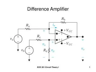
Difference Amplifier with Low Pass
Difference Amplifier with Low Pass. Tim Green Collin Wells January 30, 2013. Original Circuit Analysis. OPA277 Data Sheet Aol. OPA277 TINA SPICE Model Aol. OPA277 TINA SPICE Model Aol. Macromodel looks to be incorrect for no load phase margin.

Difference Amplifier with Low Pass
E N D
Presentation Transcript
Difference Amplifier with Low Pass Tim Green Collin Wells January 30, 2013
OPA277 TINA SPICE Model Aol Macromodel looks to be incorrect for no load phase margin. Suspect No Load phase margin to be closer to 2k load at 54 degrees.
Original Difference Amp – Vin1 Xfer Peaking in the closed loop gain is indicative of marginal stability and undesired gain of noise in the peaking region.
Original Difference Amp – Vin2 Xfer Peaking in the closed loop gain is indicative of marginal stability and undesired gain of noise in the peaking region.
Original Difference Amp – Vin1 & Vin2 Xfer Peaking in the closed loop gain is indicative of marginal stability and undesired gain of noise in the peaking region.
Original Difference Amp – Vin2 Xfer w/o C3 Without C3 the feedback capacitor C1 connection at the op amp output sees low impedance while there is loop gain to reduce Zo, open loop output impedance. As loop gain diminishes and goes to zero the open loop output impedance of 40 ohms flattens the xfer function..
Original Difference Amp – Loop Gain At 0dB Loop Gain Phase amrgin is only 4.7 degrees.
Original Difference Amp – Modified Aol & 1/Beta Cap load on output of op amp is equivalent to C1 and C3 in series or 50nF. 50nF and Zo of 40 ohms gives second pole fp2 in modified Aol. 1/Beta goes to 6dB at high frequency and at fcl rate-of-closure is 40dB/decade Indicating stability problem.
New Difference Amp – Vin1 & Vin2 Xfer New circuit will fix stability problem and give good xfer function for Vin1 and Vin2. Split resistor on VIn2 side and isollate cap load on output of op amp. Only need extra roll-off at highr frequnecies where loop gain goes to zero so can reduce value of C3.
New Difference Amp – Vin1 & Vin2 Xfer New Xfer curves for Vin1 and Vin 2 show excellent symmetry out to very high frequency with no sharp peaking.
New Difference Amp – Loop Gain Macromodel looks to be incorrect for no load phase margin. Suspect No Load phase margin to be closer to 2k load at 54 degrees And real New Circuit to have 54 degees of phase margin.
New Difference Amp – Modified Aol & 1/Beta Modified Aol is still about 20dB/decade crossing 0dB. 1/Beta intersection is about 20dB/decade indicating good stability.
Further Reading on Zo and Stability http://www.en-genius.net/site/zones/acquisitionZONE/technical_notes/acqt_050712