Download
1 / 74
800 likes | 1.14k Vues
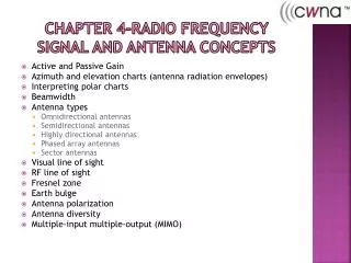
RF Signal and Antenna. Dr. Tahseen Al-Doori. Objectives. Active and Passive Gain Azimuth and Elevation Chart Beamwidth Antenna Types Visual line of sight RF line of sight Fresnel Zone. Antenna Polarization Antenna Diversity Multi-Input-Multi-Output (MIMO).

E N D
RF Signal and Antenna Dr. Tahseen Al-Doori
Objectives • Active and Passive Gain • Azimuth and Elevation Chart • Beamwidth • Antenna Types • Visual line of sight • RF line of sight • Fresnel Zone Dr. Tahseen Al-Doori
Antenna Polarization • Antenna Diversity • Multi-Input-Multi-Output (MIMO) Dr. Tahseen Al-Doori
The installation of antennas has the greatest ability to affect whether the communication is successful or not. • Antenna installation can be as easy as placing an access point in your office or it can be as complex as installing an assortment of directional antennas. • With the proper understanding of antennas and how they function, successful planning for and installing them in a wireless network will become a skillful and rewarding task. Dr. Tahseen Al-Doori
Active and Passive Gain • You can increase the signal that is radiated out of the antenna (EIRP), by increasing the output of the transmitter, which in turn increase the amount of power provided by the antenna (Intentional Radiator) and thus the amount of power from the antenna (EIRP). • This increase is referred to as Active Gain. Dr. Tahseen Al-Doori
When power is focused, the amount provided to the antenna does not change. It is the antenna acting like a lens on a flashlight that increase the power output by concentrating the RF signal in a specific direction. • Since the gain was created by shaping or directing the signal, and not by increasing the overall power, this increase is referred to as Passive gain. • Passive gain is caused by focusing the existing power, while the active gain is caused by adding more power. Dr. Tahseen Al-Doori
Azimuth and Elevation Chart • There are many antenna types designed for many different purposes, just as there are many types of lights designed for many purposes. • It is easy to see the different lights by lighting them on, unfortunately, in the case of antennas that is not the case. Dr. Tahseen Al-Doori
With the antenna measurements you need to walk around the antenna with an RF meter, take measurements and then plot it on piece of paper to find out the behavior of the RF Signal. This is a time consuming task and the results will be affected by the interference of many objects. Therefore, the manufacturers create azimuth charts and elevation charts. Which is known as radiation patterns. Dr. Tahseen Al-Doori
Azimuth and elevation charts Dr. Tahseen Al-Doori
Here are a few statements that will help you interpret the radiation charts: • In either chart, the antenna is placed at the middle of the chart. • Azimuth chart = H-plane = top-down view • Elevation chart = E-plane = side view The outer ring of the chart usually represents the strongest signal of the antenna. The chart does not represent distance or any level of power or strength. It only represents the relationship of power between different points on the chart. Dr. Tahseen Al-Doori
One way to think of the chart is to consider the way a shadow behaves. • If you were to move a flashlight closer or farther from your hand, the shadow of your hand would grow larger or smaller. The size of the shadow does not represent the size of the hand. The shadow only shows the relationship between the hand and the fingers. • With an antenna, the radiation pattern will grow larger or smaller depending upon how much power the antenna receives, but the shape and the relationships represented by the patterns will always stay the same. Dr. Tahseen Al-Doori
Beamwidth • Is the measurement of how broad or narrow the focus of an antenna is and is measured both horizontally and vertically. • It is the measurement from the center, or strongest point, of the antenna signal to each of the points along the horizontal and vertical axes where the signal decreases by half power (–3 dB), as seen in the Fig. below Dr. Tahseen Al-Doori
These –3 dB points are often referred to as half power points. The distance between the two half power points on the horizontal axis is measured in degrees, giving the horizontal beamwidth measurement. The distance between the two half power points on the vertical axis is also measured in degrees, giving the vertical beamwidth measurement. Dr. Tahseen Al-Doori
Antenna Types There are three main categories of antennas: • Omni-directional: radiate RF in a fashion similar to the way a table or floor lamp radiates light. They are designed to provide general coverage in all directions. • The small rubber dipole antenna, often referred to as a “rubber duck” antenna, is the classic example of an omni-directional antenna and is the default antenna of most access points. • The closest thing to an isotropic radiator is the omni-directional dipole antenna. Dr. Tahseen Al-Doori
An easy way to explain the radiation pattern of a typical omni-directional antenna is to hold your index finger straight up (this represents the antenna) and place a donut on it as if it were a ring (this represents the RF signal). • If you were to slice the Donut in half horizontally, as if you were planning to spread butter on it, the cut surface of the Donut would represent the azimuth chart, or H-plane, of the omni-directional antenna. If you took another Donut and sliced it vertically instead, essentially cutting the hole that you are looking through in half, the cut surface of the Donut would now represent the elevation, or E-plane, of the omni-directional antenna. Dr. Tahseen Al-Doori
We have learned that antennas can focus or direct the signal that they are transmitting. • It is important to know that the higher the dBi or dBd value of an antenna, the more focused the signal. • When discussing omni-directional antennas, it is not uncommon to initially question how it is possible to focus a signal that is radiated in all directions. • With higher-gain omni-directional antennas, the vertical signal is decreased and the horizontal power is increased. Dr. Tahseen Al-Doori
The Fig. below shows the elevation view of three theoretical antennas. Notice that the signal of the higher-gain antennas is elongated, or more focused horizontally. The horizontal beamwidth of omni-directional antennas is always 360 degrees, and the vertical beamwidth ranges from 7 to 80 degrees, depending upon the particular antenna. Dr. Tahseen Al-Doori
Because of the narrower vertical coverage of the higher-gain omni-directional antennas, it is important to carefully plan how they are used. Placing one of these higher-gain antennas on the first floor of a building may provide good coverage to the first floor, but because of the narrow vertical coverage, the second and third floors may receive minimal signal. • In some installations you may want this; in others you may not. Indoor installations typically use low-gain omni-directional antennas with gain of about 2.14 dBi. Dr. Tahseen Al-Doori
Antennas are most effective when the length of the element is an even fraction (such as 1/4 or 1/2) or a multiple of the wavelength (λ). • A 2.4 GHz half-wave dipole antenna consists of two elements, each 1/4λ in length (about 1 inch), running in the opposite direction from each other. Dr. Tahseen Al-Doori
Omni-directional antennas are typically used in point-to-multipoint environments. • The omni-directional antenna is connected to a device (such as an access point) that is placed at the center of a group of client devices, providing central communications capabilities to the surrounding clients. • High-gain omni-directional antennas can also be used outdoors to connect multiple buildings together in a point-to-multipoint configuration. Dr. Tahseen Al-Doori
A central building would have an omni-directional antenna on its roof, and the surrounding buildings would have directional antennas aimed at the central building. In this configuration, it is important to make sure that the gain of the omni-directional antenna is high enough to provide the coverage necessary but not so high that the vertical beamwidth is too narrow to provide an adequate signal to the surrounding buildings. Dr. Tahseen Al-Doori
The Fig. below shows an installation where the gain is too high. The building to the left will be able to communicate, but the building on the right is likely to have problems. Dr. Tahseen Al-Doori
Semi-directional: radiate RF in a fashion similar to the way a wall sconce is designed to radiate light away from the wall or the way a street lamp is designed to shine light down on a street or a parking lot, providing a directional light across a large area. • Semi-directional antennas are used for short- to medium-distance communications, with long-distance communications being served by highly-directional antennas Dr. Tahseen Al-Doori
There are three types of antennas that fit into the semi-directional category: • Patch • Panel • Yagi (pronounced “YAH-gee”) • Patch and panel antennas are more accurately classified or referred to as planar antennas. Dr. Tahseen Al-Doori
The exterior of a patch antenna and the internal antenna element Dr. Tahseen Al-Doori
These antennas can be used for outdoor point-to-point communications up to about a mile but are more commonly used as a central device for indoor point-to-multipoint communications. • It is common for patch or panel antennas to be connected to access points to provide directional coverage within a building. • Planar antennas can be used effectively in libraries, warehouses, and retail stores with long aisles of shelves. Dr. Tahseen Al-Doori
Due to the tall, long shelves, omni-directional antennas often have difficulty providing RF coverage effectively. • In contrast, planar antennas can be placed high on the side walls of the building, aiming through the rows of shelves. • The antennas can be alternated between rows with every other antenna being placed on the opposite wall. Since planar antennas have a horizontal beamwidth of 180 degrees or less, a minimal amount of signal will radiate outside of the building. With the antenna placement alternated and aimed from opposite sides of the building, the RF signal is more likely to radiate down the rows, providing the necessary coverage. Dr. Tahseen Al-Doori
Planar antennas are also often used to provide coverage for long hallways with offices on each side or hospital corridors with patient rooms on each side. • A planar antenna can be placed at the end of the hall and aimed down the corridor. A single planar antenna can provide RF signal to some or all of the corridor and the rooms on each side and some coverage to the floors above and below. • How much coverage will depend upon the power of the transmitter, the gain and beamwidth (both horizontal and vertical) of the antenna, and the attenuation properties of the building. Dr. Tahseen Al-Doori
Using semi-directional antennas indoors often reduces reflections, thus minimizing some of the negative effects of multipath such as data corruption. Dr. Tahseen Al-Doori
Yagi antennas are not as unusual as they sound. • The traditional television antenna that is attached to the roof of a house or apartment is a yagi antenna. The television antenna looks quite different because it is designed to receive signals of many different frequencies (different channels) and the length of the elements vary according to the wavelength of the different frequencies. Dr. Tahseen Al-Doori
A yagi antenna that is used for 802.11 communications is designed to support a very narrow range of frequencies, so the elements are all about the same length. • Yagi antennas are commonly used for short- to medium-distance point-to-point communications of up to about 2 miles, although high-gain yagi antennas can be used for longer distances. Dr. Tahseen Al-Doori
The exterior of a yagi antenna and the internal antenna element Dr. Tahseen Al-Doori
Another benefit of semi-directional antennas is that they can be installed high on a wall and tilted downward toward the area to be covered. • This cannot be done with an omni-directional antenna without causing the signal on the other side of the antenna to be tilted upward. Since the only RF signal that radiates from the back of a semi-directional antenna is incidental, the ability to aim it vertically is an additional benefit. Dr. Tahseen Al-Doori
Highly directional: radiate RF in a fashion similar to the way a spotlight is designed to focus light on a flag or a sign. Each type of antenna is designed with a different objective in mind. • Highly-directional antennas are strictly used for point-to-point communications, typically to provide network bridging between two buildings. They provide the most focused, narrow beamwidth of any of the antenna types. Dr. Tahseen Al-Doori
There are two types of highly-directional antennas: • Parabolic dish and grid antennas. • The parabolic dish antenna is similar in appearance to the small digital satellite TV antennas that can be seen on the roofs of many houses. • The grid antenna resembles the rectangular grill of a barbecue, with the edges slightly curved inward. The spacing of the wires on a grid antenna is determined by the wavelength of the frequencies that the antenna is designed for. Dr. Tahseen Al-Doori
Because of the high gain of highly-directional antennas, they are ideal for long-distance communications as far as 35 miles (58 km). Due to the long distances and narrow beamwidth, highly-directional antennas are affected more by antenna wind loading, which is antenna movement or shifting caused by wind. Even slight movement of a highly-directional antenna can cause the RF beam to be aimed away from the receiving antenna, interrupting the communications. In high-wind environments, grid antennas, due to the spacing between the wires, are less susceptible to wind load and may be a better choice. Dr. Tahseen Al-Doori
Another option in high-wind environments is to choose an antenna with a wider beamwidth. • In this situation, if the antenna were to shift slightly, due to its wider coverage area, the signal would still be received. No matter which type of antenna is installed, the quality of the mount and antenna will have a huge effect in reducing wind load. Dr. Tahseen Al-Doori
Phased Array • A phased array antenna is actually an antenna system and is made up of multiple antennas that are connected to a signal processor. • The processor feeds the individual antennas with signals of different relative phases, creating a directed beam of RF signal aimed at the client device. • Because it is capable of creating narrow beams, it is also able to transmit multiple beams to multiple users simultaneously. Phased array antennas do not behave like other antennas since they can transmit multiple signals at the same time. Because of this unique capability, they are often regulated differently by the local RF regulatory agency. Dr. Tahseen Al-Doori
Sector Antennas • Sector antennas are a special type of high-gain, semi-directional antennas that provide a pie-shaped coverage pattern. • These antennas are typically installed in the middle of the area where RF coverage is desired and placed back to back with other sector antennas. Individually, each antenna services its own piece of the pie, but as a group, all of the pie pieces fit together and provide omni-directional coverage for the entire area. Dr. Tahseen Al-Doori
Unlike other semi-directional antennas, a sector antenna generates very little RF signal behind the antenna (back lobe) and therefore does not interfere with the other sector antennas that it is working with. • The horizontal beamwidth of a sector antenna is from 60 to 180 degrees, with a narrow vertical beamwidth of from 7 to 17 degrees. • Sector antennas typically have a gain of at least 10 dBi. Dr. Tahseen Al-Doori
Installing a group of sector antennas to provide omni-directional coverage for an area provides many benefits over installing a single omni-directional antenna. • To begin with, sector antennas can be mounted high over the terrain and tilted slightly downward, with the tilt of each antenna at an angle appropriate for the terrain it is covering. Omni-directional antennas can also be mounted high over the terrain; however, if an omni-directional antenna is tilted downward on one side, the other side will be tilted upward. Dr. Tahseen Al-Doori
Since each antenna covers a separate area, each antenna can be connected to a separate transceiver and can transmit and receive independently of the other antennas. • This would provide the capability for all of the antennas to be transmitting at the same time, providing much greater throughput. • A single omni-directional antenna would be capable of transmitting to only one device at a time. • The last benefit of the sector antennas over a single omni-directional antenna is that the gain of the sector antennas is much greater than the gain of the omni-directional antenna, providing a much larger coverage area. Dr. Tahseen Al-Doori
Sector antennas are used extensively for cellular telephone communications and are starting to be used for 802.11 networking. • Example: As you walk or drive around your town or city, look for radio communications towers that are around your neighborhood. Many of these towers have what appear to be rings of antennas around them. These rings of antennas are sector antennas. If a tower has more than one grouping or ring around it, then there are multiple cellular carriers using the same tower. Dr. Tahseen Al-Doori
Visual Line of Sight • When light travels from one point to another, it travels across what is perceived to be an unobstructed straight line, known as visual line of sight (LOS). • For all intents and purposes, it is a straight line, but due to the possibility of light refraction, diffraction, and reflection, there is a slight chance that it is not. If you have been outside on a summer day and looked across a hot parking lot at a stationary object, you may have noticed that because of the heat rising from the pavement, the object that you were looking at seemed to be moving. This is an example of how visual LOS is sometimes altered slightly. • When it comes to RF communications, visual LOS has no bearing on whether the RF transmission is successful or not. Dr. Tahseen Al-Doori
RF Line of Sight • Point-to-point RF communication also needs to have an unobstructed line of sight between the two antennas. • So the first step for installing a point-to-point system is to make sure that from the installation point of one of the antennas, you can see the other antenna. • Unfortunately, for RF communications to work properly, this is not sufficient. An additional area around the visual LOS needs to remain clear of obstacles and obstructions. • This area around the visual LOS is known as the Fresnel zone and is often referred to as RF line of sight. Dr. Tahseen Al-Doori
Fresnel Zone • The Fresnel zone (pronounced “FRUH-nel”; the s is silent) is an imaginary Rugby ball-shaped area that surrounds the path of the visual LOS between two point-to-point antennas. The fig.shows an illustration of the Fresnel zone’s rugby ball-like shape. Dr. Tahseen Al-Doori
Theoretically, there are an infinite number of Fresnel zone’s. The closest ellipsoid is known as the first Fresnel zone, the next one is the second Fresnel zone, and so on. • For simplicity’s sake, and since they are the most relevant for this section, only the first two Fresnel zones are displayed in the figure. The subsequent Fresnel zones have very little effect on the communications. Dr. Tahseen Al-Doori
The fig. below illustrates a link that is 1 mile long. The top solid line is a straight line from the center of one antenna to the other. The dotted line shows 60 percent of the bottom half of the Fresnel zone. The bottom solid line shows the bottom half of the first Fresnel zone. The trees are potential obstructions along the path. Dr. Tahseen Al-Doori
The typical obstacles that you are likely to encounter are trees and buildings. • It is important to periodically visually check your link to make sure that trees have not grown into the Fresnel zone or that buildings have not been constructed that encroach into the Fresnel zone. Do not forget that the Fresnel zone exists below, to the sides, and above the visual LOS. If the Fresnel zone does become obstructed, you will need to either move the antenna (usually raise it) or remove the obstacle. Dr. Tahseen Al-Doori
To determine if an obstacle is encroaching into the Fresnel, you will need to learn a few formulas that will allow you to calculate its radius. • We are only concerned with the following formula as it calculate the radius of the first Fresnel zone at the mid-point between the two antennas. This is the point where the Fresnel zone is the largest. This formula is as follows: Dr. Tahseen Al-Doori