Download
1 / 60
620 likes | 944 Vues
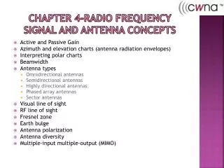
Chapter 4-Radio Frequency signal and Antenna Concepts. Active and Passive Gain Azimuth and elevation charts (antenna radiation envelopes) Interpreting polar charts Beamwidth Antenna types Omnidirectional antennas Semidirectional antennas Highly directional antennas Phased array antennas

E N D
Chapter 4-Radio Frequency signal and Antenna Concepts • Active and Passive Gain • Azimuth and elevation charts (antenna radiation envelopes) • Interpreting polar charts • Beamwidth • Antenna types • Omnidirectional antennas • Semidirectional antennas • Highly directional antennas • Phased array antennas • Sector antennas • Visual line of sight • RF line of sight • Fresnel zone • Earth bulge • Antenna polarization • Antenna diversity • Multiple-input multiple-output (MIMO)
Exam Essentials • Understand passive and active gain • Understand how antennas provide passive gain and how transceivers and amplifiers provide active gain. • Know the different categories and types of antennas, how they radiate signals, and what type of environment they are used in. • Make sure you know the three main categories of antennas and the different types of antennas. know the similarities and differences between them, and understand when and why you would use one antenna over another. Make sure that you understand azimuth and elevation charts, beamwidth, antenna polarization, and antenna diversity.
Exam Essentials • Fully understand the Fresnel zone. • Make sure you understand all of the issues and variables involved with installing point-to-point communications. You are not required to memorize the Fresnel zone or earth bulge formulas; however, you will need to know the principles regarding these topics and when and why you would use the formulas. • Understand the concerns associated with connecting and installing antennas and the antenna accessories. • Every cable, connector, and device between the transceiver and the antenna affects the signal that gets radiated from the antenna. Understand which devices provide gain and which devices provide loss. Understand what vSWR is and what values are good or bad. know the different antenna accessories, what they do, and why and when you would use them.
Signal and Antenna Concepts • Signal must be radiate with enough power so that is will be understood by the receiver • Antenna installation will have a great effect. • Simple-omni-directional in middle of office • Complex-multiple semi-directional antennas Pg 107
Active and Passive Gain • Measurements of the increase in signal from the Antenna (EIRP) • If gain is from an amplifier or increased power at the transmitter-it is ACTIVE Gain • If from shaping or focusing the power with an antenna,-PASSIVE Gain • Passive gain from focusing existing Power • Active Gain by adding more power Pg 107
Passive Gain • Focusing isotropic energy in a specific pattern • Created by the design of the antenna • Uses the magnify glass concept
Active Gain • Providing an external power source • Amplifier • High gain transmitters
Azimuth and Elevation Charts • Charts help you “see” how antennas focus energy • Polar charts or antenna radiation envelopes Pg 109
Azimuth and Elevation Charts • In either chart, the antenna is placed at the middle of the chart. • Azimuth chart = H-plane = top-down view • Elevation chart = E-plane = side view • Like casting a shadow with your hand • Shape is same, but size grows with power. Pg 109
Interpreting Polar Charts • Easy to misinterpret • The chart shows the DECIBEL mapping of coverage • Each line 5 dB!! • Normalized charts appear very different Pg 110
Interpreting Polar Charts • Easy to misinterpret • The chart shows the DECIBEL mapping of coverage • Each line 5 dB!! • Normalized charts appear very different Pg 110
Beamwidth • The measure of how broad or narrow the focus of an antenna is • Measured both horizontally and vertically • To the point where the signal decreases by half power (-3dB) Pg 113
Reading a chart • First determine the scale of the polar chart. On this chart, you can see that the solid circles represent the –10, –20, and –30 dB lines, and the dotted circles therefore represent the –5, –15, and –25 dB line • Now to determine the beamwidth of this antenna, frst locate the point on the chart where the antenna signal is the strongest. In this example, the signal is strongest where the number 1 arrow is pointing. Move along the antenna pattern away from the peak signal (as shown by the two number 2 arrows) until you reach the point where the antenna pattern is 3 dB closer to the center of the diagram (as shown by the two number 3 arrows). • This is why you needed to know the scale of the chart first. Draw a line from each of these points to the middle of the polar chart (as shown by the dark dotted lines) and measure the distance in degrees between these lines to calculate the beamwidth of the antenna. In this example, the beamwidth of this antenna is about 30 degrees. Pg 113
Antenna Types • Omnidirectional • Omnidirectional antennas radiate RF in a fashion similar to the way a table or foor lamp radiates light. They are designed to provide general coverage in all directions. • Semidirectional • Semidirectional antennas radiate RF in a fashion similar to the way a wall sconce radiates light away from the wall or the way a street lamp shines light down on a street or a parking lot, providing a directional light across a large area. • Highly directional • Highly directional antennas radiate RF in a fashion similar to the way a spotlight focuses light on a fag or a sign. Pg 115
Antenna Types • Antennas not only amplify transmitted signal, they amplify received signal Pg 115
Omnidirectional Antennas • Common on many access Points • Dipole • Rubber duck • Bagel shaped transmission • Wide horizontal coverage • Limited vertical coverage • Low gain antennas are usually 2.14dB • Higher gain is more elongated Pg 116
Low Gain Omni-directional Antenna The omni antenna is the most commonly used antenna type High Gain Omni-directional Antenna • Provides 360º horizontal coverage pattern along a flat plane. • Gain of signal along the horizontal plane means less signal along the vertical plane • Omni-directional antennas are also known as dipoles.
Antennas • Antennas are most effective when the element is an even fraction or a multiple of the wavelength (λ) • ¼, ½, 1, 2, etc. • Higher gain antennas are often made by stacking dipole antennas • Used in multipoint environments • Indoor Access Point • Building to multiple building coverage • Beware of higher gain limiting the vertical coverage Pg 117
Semidirectional Antennas • Designed to direct the signal in a specific direction • Point to point-outdoors about a mile • Down hallways • Three types • Planar Type • Patch • Panel • Yagi Pg 118
Semidirectional Antennas • Multiple planar antennas can be used to cover multiple aisles • Libraries, Warehouses, Retail, etc • Yagi antennas are like old TV antennas • However, each element is fitted for wireless wavelengths • Even fraction or multiple of wavelength Pg 119
Semidirectional Antennas • Also good on walls • Most have limited side lobe and vertical and can be pointed down for coverage Pg 121
Semi-directional Antennas Patch • Patch, Panel, Yagi and Sector are the primary semi-directional antenna types on the market today • Semi-directional antennas have 180º or less of horizontal and vertical beam width • Primary coverage uses include: • Hallways/Corridors • Wireless ISPs • PTP & PTMP Bridging Patch Multiple semi-directional antennas can be combined into an array to provide omni-directional coverage.
Highly Directional Antennas • For Point to Point • Generally between two buildings • Focused, narrow beamwidth • Two main types • Parabolic Dish • Grid Antenna • Since they are used outdoors, wind loading is an issue • Since they have narrow beamwidth, the wind can push them out of direction Pg 121
Highly Directional Antennas • Highly focused energy • Most common type - parabolic
Phased Array Antennas • Multiple antennas connected to a signal processor • Different antennas can be fed different phases • Able to create very directed beams • Usually regulated differently • Not common in 802.11 • 802.11n has a PHY specification that supports it • Smart antenna technology Pg 123
Sector Antennas • Specialized high gain, semidirectional antenna • Multiple antennas with limited back lobe • Each antenna can be on its on its own transceiver • Usually set up to provide 360 degree coverage • Used extensively in cellular phone systems Pg 123
Line of Sight • The “line” from source to destination • Visual LOS is not important on Wireless networks • RF line of sight is • Mostly for outdoor point to point connections • Should be unobstructed Pg 124
Maintaining Clear Communications • Visual line of sight • RF line of sight • Fresnel zone
Fresnel Zone • Football shaped area around the “LOS” • Actually multiple zones surrounding the main line of sight • If first Fresnel zone is obstructed, it will affect the transmissions • more than 40% will make link unrealiable • Keep it to less than 20% Pg 125
Fresnel Zone • You need to understand how the calculations will affect placement when designing a point to point. • Can calculate the size of the zone in middle • Or at certain distances • Important for keeping out obstructions Pg 125
Fresnel Zone • Don’t mistake smaller beamwidth for smaller Fresnel zone • Fresnel zone is affected by the frequency of the transmission, not the antenna Pg 128
Earth Bulge • For longer Point to Point links-More than 7 miles • Important to calculate height requirements for towers Pg 128
Antenna Polarization • Alignment of the antenna can affect polarization • Doesn’t matter if it is horizontal or vertical, both transmitter and receiver need to be the same way • Most systems have antenna diversity • Multiple antennas (more than one wavelength away) • If the Received Signal Level (RSL) is 10 to 15 dB less than expected, you may be linking to a side lobe Pg 130
Antenna Diversity • Helps compensate for multipath • An AP has multiple antennas • Compares the signal from each antenna and choose the best signal • 802.11n uses switched diversity • Signal with the best amplitude is used • Also known as received diversity • Can also use measurement to choose the transmit antenna Pg 130
Antenna Diversity • Don’t put the antennas in different locations or point in different directions • That defeats the purpose • Usually a single radio with multiple connections • Common inside laptops Pg 130
Multiple In Multiple Out (MIMO) • More sophisticated type of antenna diversity • Takes advantage of multipath • Uses Space Time Coding • Send multiple signals simultaneously Pg 132
Voltage Standing Wave Ratio (VSWR) • Measure of the change in impedances to an AC signal • When there is a difference or mismatch in impedance between devices in a RF system • Forward Energy is reflected backward to the transmitter • Usually at points where you are connecting • Cable to transmitter • Cable to antenna Pg 133
Voltage Standing Wave Ratio (VSWR) • Ratio of energy reflected is the voltage reflection coefficient • Return Loss • Ideally, there is no mismatch • A matched cable, 0 ratio, infinite return loss • VSWR is a measure between the maximum voltage and minimum voltage • VSWR=Vmax/Vmin Pg 133
Voltage Standing Wave Ratio (VSWR) • Higher the return loss, the less broadcast power • Return voltage can also damage the transmitter Pg 133
Signal Loss • The goal when connecting the antenna to transmitter is to reduce signal loss • Must pay attention to devices used • Cables and connectors Pg 134
Antenna Mounting • Placement • Mounting • Appropriate Use • Orientation and alignment • Safety • Maintenance Pg 134
Placement • Correct placement for type of antenna • Omnidirectional toward center • Semi-direction at edge, pointed toward center • Pay attention to vertical and horizontal coverage • Also, power levels- • Too high a power will provide an overlarge coverage area • Security risk • Outdoors-Watch the Fresnel Zone Pg 135
Mounting • Outdoors • Masts or towers • Indoors • Wall or ceiling • Often want to hide or camouflage for aesthetics Pg 135
Appropriate Use • Indoor vs. Outdoor • Although they look the same, they are designed for correct temperature and environment Pg 136
Orientation and Alignment • Pay attention to horizontal vs. vertical alignment • Polarization can make the difference between being able to communicate or not Pg 136
Safety • Be careful • RF health and safety courses • FCC and OSHA regulations • If installing on a tower, pole, etc-get a professional. Pg 135
Maintenance • Preventative and diagnostic • Don’t just set and forget • Especially not outdoors • Outdoors you need to be aware of wind and water damage • Wind • Properly mount • Water • Cold-shrink tubing, sealant, drip loops Pg 137
Antenna Accessories • All devices attached in the RF system need to be checked for • Frequency response • Impedance • VSWR • Maximum input power • Insertion loss Pg 137
Cables • Choose the correct cable based on technology, frequency, etc • Some cables can’t be used with some frequencies • Match the impedance • Calculate the signal loss • Different for different frequencies • Purchase pre-cut of hire a professional • You want to measure loss in the connections Pg 139
Connectors • FCC has mandated that manufacturers use unique connectors to limit the ability to use noncertified antennas • Pigtail adapters get around this requirement • Be careful of exceeding FCC regulations Pg 139