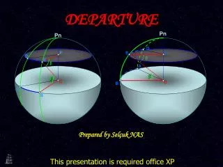
Chapter 4 Departure Charts
680 likes | 828 Vues
Learn about departure charts, their composition, and vital information for smooth takeoffs, traffic control, and fuel efficiency in aviation. Explore examples and decode departure procedures with this comprehensive guide.

Chapter 4 Departure Charts
E N D
Presentation Transcript
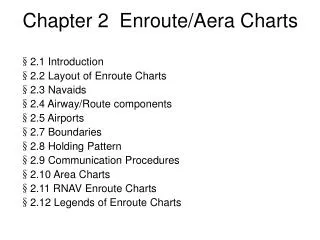
Chapter 4 Departure Charts §4.1 Introduction §4.2 Arrangement and Information of Departure Charts §4.3 Examples of Chart
§4.1 Introduction The purpose of using departure charts are • Provide a transition between the airport and the enroute structure after take off • Reduce frequency congestion, ensure obstacle clearance • Control the flow of traffic around an airport • Reduce fuel consumption, and may include noise abatement procedures
§4.2 Composition and Information of Departure Charts • Heading • Plan View
Heading PlanView
§4.2.1 Heading The heading of departure includes information about date, communications, transition level and transition altitude, departure procedures naming and numbering. Pilots could find the proper airports and departure procedures by checking the heading of departure charts.
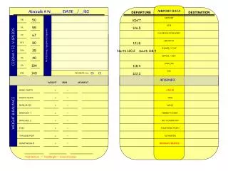
§4.2.1.1Heading Border Data The heading border data includes: • Chart procedure identifier • Location name • ICAO Airport Identifier/ICAO Location Indicator • Chart index number • Revision dates
Chart Procedure Identifier ICAO Airport Identifier/ICAO Location Indicator Location Name Chart Index Number Airport Elevation Departure Frequency Revision Date Effective Date Primary Airport Name
Chart Procedure Identifier Chart procedure identifier helps pilots quickly identify the correct type of chart(departure, arrival, approach, and so on)
Some charts provide additional information about the type of departure. For example, displays “SID(R)” in the heading ,which tells the pilot that operative ATC radar is required for the departure. Some charts use the designation “RNAV SID” to alert pilots that only aircraft with area navigation equipment can use this departure.
Location Name For civilian airports, the geographic location is usually the same as the major city it serves. Charts for military airports list the installation name first, with the city displayed below it.
Primary Airport Name At the Plainview of departure charts, the positions where the main airports locate are denoted by circular shadow.
If there is a “-” before the name of an airport, that means the location name should be a part of the main airport’s name
If one departure chart can be used at many airports, the secondary airports are listed under the main airport.
Another kind of departure chart is area departure chart. This kind of chars can serve many different airports and there is no primary and secondary.
Chart Index Number The chart index number helps pilots to sequence and locate charts within Airway Manual.
Revision dates effective date chart date If the effective date is not indicated, the chart will become effective at once.
§4.2.1.2 Communications Information about communications is displayed within a box in the heading on the left. The departure frequency may display one or more of the following frequencies: • Approach • Center • Clearance • Control • Radar
An asterisk (*) in front of the name of a frequency indicates that the service is not available at all times ; An (R) that follows the frequency type means that radar is available for that service.
§4.2.1.3 Transition Level and Transition Altitude The transition level and transition altitude are shown following the communication frame.
§4.2.1.4 Chart Naming and Numbering Generally, departure procedures are named after the last fix on the SID, which transitions the pilot to the enroute structure. Sometimes, a plan view displays more than one departure procedure. When several departures end at the same fix, they are distinguished numerically.
The code name in navigation database. It couldn't be used to fill flight plan, or communicate with ATC. ATTOL 2A and ATTOL 2C all end at ATTOL
Typically in the United States, there are transition routes that guide pilots from the departure route to a fix in the enroute structure. In these cases, the SID is usually named after the last fix on the departure and beginning of the transition. When a significant portion of a departure procedure is revised, such as an altitude, a route, or data concerning the navaid, the number of the departure changes.
For Example, the Maric Three Departure is the third version of the modifications made to this procedure.
A few departure charts, as those for Mexico, are simply named “Departures.” In front of it is the designations of applicable runways for the route charted. These charts represent preferred departure routes for the airport listed. Finally, a few airports provide initial climb-out procedures when their departure procedures are particularly complicated or detailed. These procedures provide pilots with guidance for a route from a particular airport runway to a fix that begins a published departure procedure.
With the departure name, a number of other important data may be listed: • High enroute designator • Departure code • Departure type • Runway designations • Departure direction
High Enroute Designator A “(Hi)” designation displayed with the route name means that the departure procedure or transition route ends at a fix within the high altitude enroute structure.
Departure Code For charts that depict airports that have computerized their route identification for flight planning/filing purposes, the computer code for a particular departure procedure displays in circinal brackets following the route name.
Departure Type When listed, the type of departure follows the name of the route. Departure types could be PILOT NAV, RNAV, VECTOR, DME, or GPS.
Runway Designations If a departure applies to specific runways, they are listed below the title. Otherwise, they are specified in the plan view of the chart.
Departure Direction Many large airports have different routes designated for aircraft headed for specific airways or cardinal headings.
§4.2.1.5 Chart Restrictions The chart title may include any number of restrictions, such as: • Kind of airplane • Speed • Kind of equipment • Noise abatement
Kind of Airplane Some routes are designated specifically for jet, turboprop, or non-turbojet airplanes.
Speed Restrictions on speed are often noted in a reverse-type box with several criteria for the pilot to follow.
Kind of Equipment Since departures can be simplified with the use of navigation systems, RNAV SIDs often specify the kind of equipment required to fly that departure.
Noise Abatement When special procedures exist for noise abatement purposes, they are often referenced with a note below the title of the departure.
§4.2.2 Plan View A pilot checks for certain instructions, such as headings, climb gradients, and altitudes, as well as speed, airspace, and noise abatement restrictions.
The direction of this symbol represents the north direction. It always point to the up side of a departure chart. “NOT TO SCALE” means that the chart is not plotted to scale. But the geography positions and direction information are precise.
§4.2.2.1 Airports The primary airport is displayed in the plan view by a shaded circular area. Within the Primary airport symbol is a depiction of the airport’s runways. The chart shows the runway orientation and relative runway lengths. Sometimes, the departure chart for a particular airport includes other airports in the vicinity. The symbol used for the secondary airport depends on whether the airport is civilianor military.
民用卫星机场 Civilian airport 军用卫星机场 Military airport
§4.2.2.2 Navaid and Fixes Departure routes are defined by various navigation facilities in the area. Typically, the departure chart shows all the navaids that define the route within the plan view section of the chart. Along the route, there may be designated locations that provide a means for checking the progress of the flight. These fixes may be defined by their relative position to various navaid, as well as latitude and longitude positioning. Departure charts use a variety of symbols to depict the different navigation facilities and fixes.
§4.2.2.3 Flight Tracks Departure plan view includes graphic symbols that portray the various tracks and transitions served by the procedure. • A bold-lined arrow indicates the SID track • A bold dashed line represents transition tracks If there are more than one transition procedures in a departure chart, the names of transition procedures should be denoted near the transition tracks. Meanwhile, corresponding textual explanation should be contained in the departure chart.
A thin, real line with arrows represents VOR Radials or NDB bearing • A thin, curved line represents a DME arc. The DME arc is not the real track. It can be used to indicate the change of heading and altitude, or the restriction line when turning. The unit “NM” is labeled on the DME arc.
If there is a route identification code near the departure track, it means that the departure track is a part of this route. • A series of small arrows represents radar vectoring .That means pilots could obtain radar vectoring . • Some textual description about SID track and altitude information.
When there are several departure procedures in a chart, the SID names are used near by the track to denote which departure procedure the track belongs to. Information about flight track and altitude of the corresponding procedure can be found in the table at the bottom or the plan view of chart.
Radar Vectoring DME Arc SID Track Route identification code VOR Radial Transition Procedures Name Transition Track
SID Name SID textual description
§4.2.2.4 Departure Elements Textual descriptions about route and altitude of departure often accompany the graphics on the plan view of a chart.
Take-off minimums Initial climb Routing