Download
1 / 27
390 likes | 1.96k Vues
Simulink Based Vehicle Cooling System Simulation; Series Hybrid Vehicle Cooling System Simulation 13 th ARC Annual Conference May 16, 2007 SungJin Park , Dohoy Jung, and Dennis N. Assanis University of Michigan. Outline. Introduction Motivation Objectives Simulation and Integration

E N D
Simulink Based Vehicle Cooling System Simulation; Series Hybrid Vehicle Cooling System Simulation 13th ARC Annual Conference May 16, 2007 SungJin Park, Dohoy Jung, and Dennis N. Assanis University of Michigan
Outline • Introduction • Motivation • Objectives • Simulation and Integration • Hybrid vehicle system modeling [VESIM] • Cooling system modeling • Configuration of HEV cooling system • Summary
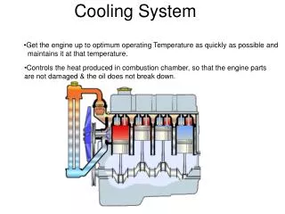
Vehicle thermal management and cooling system design • Motivation • Additional heat sources (generator, motor, power bus, battery) • Various requirements for different components • Objective • Develop the HEV Cooling System Simulation for the studies on the design and configuration of cooling system • Optimize the design and the configuration of the HEV cooling system Conventional Cooling System HEV Cooling System
Overview of Cooling System Simulation • Cooling system model use simulation data from the hybrid system model • Minimizes computational cost for optimization of design and configuration Driving schedule HEV Cooling System Model Hybrid Propulsion System Model [VESIM]
Power Bus Motor Generator Engine Battery Wheel Hybrid propulsion system configuration and VESIM Generator Power Bus Engine Controller Battery Motor Vehicle
Hybrid vehicle power management Charging mode Braking mode Discharging mode • Engine / generator is the primary power source • When battery SOC is lower than limit, engine supplies additional power to charge the battery • Once the power demand is determined, engine is operated at most efficient point • Battery is the primary power source • When power demand exceeds battery capacity, the engine is activated to supplement power demand • Regenerative braking is activated to absorb braking power • When the braking power is larger than motor or battery limits, friction braking is used
Vehicle simulation Vehicle simulation model [VESIM] Vehicle driving cycle Cycle simulation results ( engine / generator / motor / battery) Battery SOC Motor Speed Engine Speed Generator Speed Generator Torque Engine BMEP Motor Torque
Cooling system modeling;Configurations Configuration A Motor PowerBus Generator Parallel Circuit Electric Pump Radiator1 Parallel Circuit CAC1 Turbo Charger Engine Engine Block T/S Oil Cooler CAC2 Mech. Pump A/C Condenser T/S Mech. Pump Radiator2 Fan Radiator Fan HEV Cooling System Model in Matlab Simulink
Guide Lines of Cooling system configuration Criteria for system configuration • Radiators for different heat source components are allocated in two towers based on operation group • The radiators are arranged in the order of maximum operating temperature • Electric pumps are used for electric heat sources • The A/C condenser is placed in the cooling tower where the heat load is relatively small • Battery is assumed to be cooled by the compartment A/C system due to its low operating temperature (Lead-acid: 45oC)
Configurations Configuration C Configuration B Power Generation Vehicle Propulsion
Modeling Approach: Heat source • Heat Input and Exchange Model for Engine Block and Electric Components • Lumped thermal mass model • Heat transfer to cooling path (Qint) and to outer surface (Qext; radiation and natural convection) • Engine • Map based engine performance model • Heat rejection rate as a function of speed and load is provided by map • Turbo Charger • Map base turbo charger performance model • The temperature and flow rate of the charge air as functions of speed and load are provided by map Schematic of Heat Exchange Model at Engine and Electric components Engine heat rejection rate
Modeling Approach:Heat sources (cont.) • Oil Cooling Circuit • Heat addition model : heat is directly added to the oil • Heat rejection rate as a function of speed and load is provided by map • Condenser • Heat addition model: heat is directly added to the cooling air • Constant value is used for heat rejection rate • Charge air coolers • 2-D FDM-based model • In contrast to radiator, heat transfer occurs from air to coolant • Generator • Heat generation is calculated using a 2D look-up table indexed by speed and input torque • Lumped thermal mass model
Modeling Approach:Heat sources (cont.) • Motors • Heat generation is calculated using a 2D look-up table indexed by speed and input torque • Lumped thermal mass model • Power bus • Power bus regulates the power from electric power sources and supply the power to electric power sink • Heat generation is determined by battery and motor power • Lumped thermal mass model
Modeling Approach:Heat sinks Structure of a typical CHE • Heat exchanger (radiator) • Design variables • Core size • Water tube : depth, height, thickness • Fin : depth, length, pitch, thickness • Louver : length, height, angle, pitch • Based on thermal resistance concept • 2-D Finite Difference Method Design parameters of CHE core Empirical correlation for ha (by Chang and Wang) Staggered grid system for FDM
Modeling Approach:Heat sinks(cont.) • Oil cooler • Finned concentric pipe heat exchanger model for Oil Cooler • Counter flow setup • NTU approach is used to calculate the exit temperature of two fluids Schematic of Heat Exchange at Engine and Electric components NTU Method
Modeling Approach:Delivery media (Coolant) • Coolant Pumps • The coolant flow rate is calculated with calculated total pressure drop by cooling system components and the pump operating speed • Performance map is used to calculate the coolant flow rate • The mechanical pump is driven by engine and electric pump is driven by electric motor Efficiency Flow rate Flow rate Efficiency Performance Maps of Mechanical Pump Performance Maps of Electric Pump
Modeling Approach:Delivery media (Coolant) • Thermostats • Two way valve with Hysteresis characteristics • Coolant flow rate to re-circulate circuit and radiator are determined by the pressure drops in each circuit T/S valve lift with hysteresis Valve lift curve of T/S Coolant flow calculation based on pressure drop
Modeling Approach:Delivery media (Oil/Air) • Oil Pump • Map based gear pump model for Oil Pump • Cooling fans • Total pressure drop is calculated from the air duct system model based on system resistance concept • Performance map is used to calculate the air flow rate Map Based Gear Pump Model Condenser Fan & Shroud Grille Radiator 1,2
Test conditions • Test condition for sizing components and evaluating cooling system configuration • The thermal management system should be capable of removing the waste heat generated by the hardware under extreme operating condition • Grade load condition is found to be most severe condition for cooling system Off-Road Maximum Speed Grade Load Ambient Temperature 40 oC Road profile of off-road condition
Configuration test;Grade Load (30 MPH, 7 %) Engine Speed Engine BMEP Battery SOC Grade Load Max. SOC: 0.7 Min. SOC: 0.6 Initial SOC: 0.6
Configuration A and B • Config. A could not meet the cooling requirements of electric components Configuration B Configuration A Generator Generator Motor Motor PowerBus PowerBus
Configuration A and B Configuration B Configuration A • Performance of one CAC in Config. B was better than that of two CAC in Config. A CAC1 CAC CAC2
Configuration B and C Configuration C Configuration B • Config. C is designed by adding a coolant by-pass line to Oil Cooler in Config. B • Power consumption of pump is reduced by 5% adding the bypass circuit
Summary • The HEV Cooling System Simulation is developed for the studies of the cooling system design and configuration • The HEV cooling systems are configured using the simulation • In hybrid vehicle, the heat rejection from electric components is considerable compared with the heat from the engine ( Grade Load : heat from electric components ≈ 98kW, heat from engine module ≈ 240kW) • Proper configuration of cooling system is important for hybrid vehicle components, because the electric components work independently and have different target operating temperatures • Parasitic power consumption by the cooling components can be reduced by optimal configuration design • Optimization study of cooling system is conducted using developed model (Symposium II, “Optimal design of electric-hybrid powertrain cooling system”)
Acknowledgement • General Dynamics, Land Systems (GDLS)