STAR Forward GEM Tracker Readout/DAQ Integration
50 likes | 166 Vues
This document outlines the modular readout crate architecture designed for the Forward GEM Tracker at the Indiana University Cyclotron Facility. It details the integration of remote regulated DC power supplies, ARM (APV Readout Modules), and ARC (APV Readout Controllers), as well as their communication through a passive backplane. The setup involves 12 cables and 10 APVs per cable, totaling 15,360 detector channels per crate, demonstrating a robust system capable of high-performance data acquisition and signal processing while maintaining magnetic field tolerance.

STAR Forward GEM Tracker Readout/DAQ Integration
E N D
Presentation Transcript
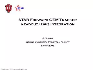
STAR Forward GEM Tracker Readout/DAQ Integration G. Visser Indiana University Cyclotron Facility 5/16/2008
Modular readout crate architecture backplane Remote regulated DC power ARM ARM ARM ARM ARM ARM ARC ALICE SIU (mezzanine board) Optical fiber to D-RORC 7 pair cable or optical fiber from STAR TCD Signal & Power cables, ≈ 8.3 m, to APV Connector/Motherboards • Two crates, each handles 12 cables, 10 APV’s per cable, a total of 15360 detector channels per crate • ARM (APV Readout Module): 20 ADC channels and data processing FPGA’s (zero suppression, pileup rejection); power for APV on ARM or separate new board (4/crate) • ARC (APV Readout Controller): control FPGA’s, STAR clock/trigger interface and ALICE SIU (data/control link) • Connected by passive backplane, 30 MHz synchronous 24 bit datapath • Uses commercial hardware (6U crate, VME P1 backplane) • Crates mounted on west end ring of STAR magnet, e.g., in former location of SVT crate; magnetic field tolerant design
FGT DC Power and Grounding south platform 2nd level readout crate (only 1 shown here) +1.8 V @ 0.90 A, -1.8 V @ 1.56 A +6 V @ 36 A, -6 V @ 22 A APV Motherboard assy. (1 of 24 shown here) 24 m ARM (only 1 shown here) 4x 4AWG 8.3 m Isolated dual DC supply (Wiener PL-508) 3x 20AWG Low-dropout low noise regulator +/-1.25V APV25 ASIC’s Quasi-isolated output +/-1.8V regulator sense lines 4C 18AWG 20AWG FEE GND OPTION JUMPER readout crate backplane GEM bias divider / bypass caps Local loads, not detailed here PREFERRED FEE GND OPTION STAR GND (magnet steel) STAR GND (TPC structure) Non-isolated HV DC supply Inside, at detector HV coax, shown here as two lines for clarity
(Stock) Cables from ARM to ACB/AMB • Power & ground, 7C #20 AWG – Belden #5405FE, 5.1mm dia., 56.7 g/m • +1.8 V force • +1.8 V sense • power return “ground” force • ground sense • -1.8 V force • -1.8 V sense • detector ground connection • foil shield w/ #22 AWG drain wire • Control & signal, 18Pair (3 unused) #28 AWG – Alpha #6398 or Belden #9819, 9.8mm dia., estimated 112 g/m • CLK to ACB/AMB • CLK loopback from ACB (arrives at ADC automatically in time w/ signals) • TRG • APV signals to RDO (10 pairs) • I2C SDA/GND • I2C SCLK/GND • foil shield w/ #28 AWG drain wire, and tinned copper braid (rather not have it) • Total cross-section passing last FGT disk: 19.2 cm2 (20 power & 20 signal cables), total mass about 5.5 kg
APV analog output driving a long cable In contrast to CMS, we will send the APV analog signals a considerable distance (8.3 m) from the detector, with no buffering or optical conversion at the detector. APV ONLY – NO CABLE – 110 Ω LOAD 19 m PVC CABLE IN/OUT (DOUBLE TERMINATED, AD8129 RECV.) 1 1 10 1 0 1 0 1 0 01 The APV “digital” header provides a convenient test pattern CABLE OUT (DOUBLE TERMINATED, AD8129 RECV., EQ.) Noise level <0.7 mV RMS, i.e., >11.5 bit dynamic range With equalization, full swing is restored, sample-sample crosstalk almost completely cancelled, within 1 sample time (56 ns) Remaining <1% sample-sample crosstalk may be robustly removed with FIR digital filter Works fine, even in this test w/ more than double the planned length (ok we could even consider to allow longer cable if we must… I’d like to know this soon!)