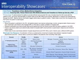
Device Integration
Device Integration. A Practical Guide to Device Integration with an emphasis on the Modbus Serial Protocol. Goals for this Presentation Provide information on the steps required for successful device integration implementation.

Device Integration
E N D
Presentation Transcript
Device Integration A Practical Guide to Device Integration with an emphasis on the Modbus Serial Protocol • Goals for this Presentation • Provide information on the steps required for successful device integration implementation. • Provide information for making decisions for selecting the proper hardware and software for the implementation. • Provide information on the types of tools that are useful for a successful implementation. E
Device Integration A Practical Guide to Device Integration with an emphasis on the Modbus Serial Protocol • What you should know before you start • Steps to successfully implement a device interface • Information on the Device to be integrated. • I/A Series products: How to choose the appropriate Hardware/Software E
Definition Design Implement Integrate Start-up Engineering Process Integration Engineering
Device Integration A Practical Guide to Device Integration with an emphasis on the Modbus Serial Protocol • Integration Definition – Foreign Device Definition • Manufacturer • Model • Communications Protocol Supported • Types of ports available • Decide on Communication parameters • Decide on Network Address • Types of Queries supported • Memory Map of desired data points • Does the device have a user mappable memory range? • Does the device have redundant communications capability? • How many devices will be on this serial bus? • How far away from the integrator will the device be? E
Device Integration A Practical Guide to Device Integration with an emphasis on the Modbus Serial Protocol • Integration Definition – Foreign Device Definition • Manufacturer • Model This is not necessarily essential information, but you may want to use some aspect of the manufacturer/Model information to name your ECB, Compound, or Control Blocks. E
Device Integration A Practical Guide to Device Integration with an emphasis on the Modbus Serial Protocol • Integration Information – Foreign Device Definition • Communications Protocol Supported I/A Series Integration Information An MG30 supports Modbus Master RTU Protocol An FBM224 Supports Modbus Master RTU Protocol An AB30 Supports Allen-Bradley DF1 protocol All other protocols require the use of the DI30 with a protocol specific software component E
Device Integration A Practical Guide to Device Integration with an emphasis on the Modbus Serial Protocol • Integration Definition – Foreign Device Definition • Types of ports available • What type of physical connector does the device have? DB9, DB25, RJ45, Terminal Strip, Male or Female • Which serial protocols are supported? RS232, RS485, RS422 Note: RS485 is the only multi-drop protocol. I/A Series Integration Information All 30 Series integrators support RS232 with a Male 25-pin D- connector. The FBM224 supports RS232 with a male 25-pin D-connector AND RS485/RS422 with terminal connections. E
Device Integration A Practical Guide to Device Integration with an emphasis on the Modbus Serial Protocol • Integration Definition – Foreign Device Definition • Decide on Communication parameters Baud Rate (Typically 9600 default) Databits (7 or 8) Parity (Even, Odd, None) Stop Bits (1 or 2) I/A Series Integrator Information Integrators support up to 19200 Baud (configurable) E
Device Integration A Practical Guide to Device Integration with an emphasis on the Modbus Serial Protocol • Integration Definition – Foreign Device Integration • Decide on Network Address This network address is specific to the protocol Modbus Specific Information The valid network address range for Modbus is between 1 and 256. 0 is a broadcast address. The Master does not have a specified address (only one master per bus). If more than one device exists on the serial bus, each must have a unique network address. E
Device Integration A Practical Guide to Device Integration with an emphasis on the Modbus Serial Protocol • Integration Definition – Foreign Device Definition • Types of Queries supported Modbus Specific Information Typically function codes 1,2,3,4,5,6,15,and 16 are supported by modbus devices Heartbeat is one query type for Modbus (function code 8) that can cause intermittent failures if the field device does not support this function. E
Device Integration A Practical Guide to Device Integration with an emphasis on the Modbus Serial Protocol • Integration Definition – Foreign Device Definition • Memory Map of desired data points Modbus Specific Information The Memory Address and whether the query is a read or a write determines function code used to obtain that information. Memory Map Read Write 0-9999 function code 1 function code 5,15 10000-19999 function code 2 N/A 40000-49999 function code 3 function code 6, 16 30000-39999 function code 4 N/A E
Device Integration A Practical Guide to Device Integration with an emphasis on the Modbus Serial Protocol • Integration Definition – Foreign Device Definition • Does the device have a user mappable memory range? Important for the efficiency of the interface in cases where the data points are not arranged in a contiguous fashion. E
Device Integration A Practical Guide to Device Integration with an emphasis on the Modbus Serial Protocol • Integration Definition – Foreign Device Definition • Does the device have redundant communications capability? This question is important to determine which software package is correct for your application. I/A Series Integrator Information The DI30 has two ports. Each can talk to a separate device or as a redundant port. The MG30 has two ports. The second can be configured as a “B” bus to the same device. The FBM224 has four ports and a redundant port can be configured. E
Device Integration A Practical Guide to Device Integration with an emphasis on the Modbus Serial Protocol • Integration Definition – Foreign Device Definition • How many devices will be on this serial bus? This question is important to decide upon the bus architecture. If only one device is on the bus, RS232, RS422, and RS485 are all valid choices. For multiple devices on the same bus, only RS485 supports multidrop. E
Device Integration A Practical Guide to Device Integration with an emphasis on the Modbus Serial Protocol • Integration Definition – Foreign Device Definition • How far away from the integrator will the device be? This question is important to ask to determine which protocol/and or converters will be required. For instance, if the distance is greater than 50 feet, then RS232 is not a good option without the use of converters. E
Device Integration A Practical Guide to Device Integration with an emphasis on the Modbus Serial Protocol • Design considerations • In today's terms, serial communications have a very low throughput. Example: Assume that a typical query takes 200 ms to reach the field device, the field device takes 100 ms to process the query and build the response message, then 200 seconds for the response to reach the integrator. That equal 500 ms turnaround per query. In essence 2 queries per second. This is why it is extremely important to gauge the total number of queries on a serial bus and use a conservative estimate for turnaround time. E
Device Integration A Practical Guide to Device Integration with an emphasis on the Modbus Serial Protocol • Design considerations • How many queries will I have? • Each Modbus device on a bus will take a minimum of one query • Each different function code (including heartbeat) requires its own query. • If memory locations are not contiguous, and a “reserved” or “restricted” memory address is between the desired data points, then more than one query will be required per query range. E
Device Integration A Practical Guide to Device Integration with an emphasis on the Modbus Serial Protocol • Design considerations • How many queries will I have? Example1: I have a device from which I wish to obtain 10 discrete data points, 10 analog values, write 10 analog values, and write 10 discrete data points. This device supports heartbeat. This interface would have five (5) queries and the update time should be set to no faster than 2.5 seconds.* *actual turnaround times can be checked with a communications probe. E
Device Integration A Practical Guide to Device Integration with an emphasis on the Modbus Serial Protocol • Design considerations • How many queries will I have? Example2: I have 2 devices on the same RS485 bus from which I wish to obtain 10 discrete data points, 10 analog values, write 10 analog values, and write 10 discrete data points each. These devices support heartbeat. This interface would have five (10) queries and the update time should be set to no faster than 5 seconds.* *actual turnaround times can be checked with a communications probe. E
Device Integration A Practical Guide to Device Integration with an emphasis on the Modbus Serial Protocol Integration Design Should you use a MG30, DI30, or a FBM224 for your implementation? An MG30 is for Modbus RTU Master protocol only, but is very easy to configure. A DI30 Can be Master or Slave, RTU or ASCII, and has settable parameters for communication timing adjustments, but is much more complex to configure. An FBM224 is easy to configure, but is also for Modbus RTU Master protocol only and is only currently available for 6.5 and 7.1 versions. E
Device Integration A Practical Guide to Device Integration with an emphasis on the Modbus Serial Protocol Integration Design In Summary, Use an FBM224 if you are at V6.5 or 7.1 and the device is a Modbus Slave. Use a MG30 if at any other version and the device is a Modbus RTU Slave. Use a DI30 if neither of the above apply. E
Device Integrator 30 Configurations Non Redundant Device Integrator Redundant Device Integrator
MG30 INTEGRATION Non Redundant Configuration Redundant Configuration
FDRIN Message FDIDMS ECB Other Blocks FDIIN FDBIN DI 30 Integration Inputs
DI 30 Integration Outputs Message FDROUT FDMSBL ECB Other Blocks FDIOUT FDBOUT
DI 30 Integration Master vs Slave Message FDSCAN ECB Master Configuration Data Message Data Scanned at regular frequency Set by FDSCAN Block Period Data Message FDIDMS ECB Slave Configuration Data Identified and used as it is sent from the Field Device
AIN ALMPRI AOUT CALC CHARC CIN COUT DEP EXC GDEV IND MAIN MCIN MCOUT MON MOVLV MTR PATALM REALM TIMR VLV MODBUS INTEGRATOR BLOCKS
COUT AOUT ECB CIN AIN ModBus 30 Integration OTHERBLOCKS MDSCAN BLOCK
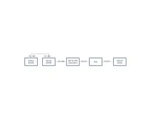
Device Integration A Practical Guide to Device Integration with an emphasis on the Modbus Serial Protocol Integration Design Create a drawing showing the architecture of the interface consisting of the following elements: Integrator Cable and FTA for the Integrator Any converters required for the interface. Identify the type of media for each cable (fiber-optic, Twin-axial, etc…) The dip-switch settings for the FTA based on the Definition information and the settings shown in each of the Integrator specific user documentation. E
Device Integration A Practical Guide to Device Integration with an emphasis on the Modbus Serial Protocol Useful Tools for Modbus Implementation Break-Out Box - This device connects in line with an RS232 bus to show signal voltage for all of the data and control lines for this protocol. Communication (data) probe – This device also connects in line with the RS232 bus to show actual bytes of data as well as showing signal voltage for all the data and control lines. E
Device Integration A Practical Guide to Device Integration with an emphasis on the Modbus Serial Protocol Useful Tools for Modbus Implementation Modbus/Modsim simulation program - This application allows you to use a laptop (or tabletop) PC to emulate a Modbus Master or Modbus Slave device respectively, and view the modbus data bytes. Null Modem Connectors – This device connects in line with the RS232 bus to correct one of the most common RS232 problems. It converts the control and data lines from a DTE to a DCE type. E
Device Integration A Practical Guide to Device Integration with an emphasis on the Modbus Serial Protocol Useful Tools for Modbus Implementation Assorted cables and connectors - Make sure that an assortment of cable types (9-pin versus 25-pin) and male-to-male and female-to-female adapters are available. Nothing stops implementation faster than not being able to physically attach a cable. If the implementation will use a RS485 bus, it is a good idea to have an extra RS232/RS485 converter available to use the RS232 only tools! Modbus Device Vendor – Many times an implementation comes to a screeching halt because no one is available that can look inside the foreign device to verify basic communications settings. So if no one is available that knows the device well, then it is best to have a vendor representative present during implementation E
Device Integration A Practical Guide to Device Integration with an emphasis on the Modbus Serial Protocol • Steps to implement the interface • Verify Foreign device is ready for communication by using Modsim or similar modbus master emulator to query a specific modbus data point. • Once you can connect with this program, you can consider the foreign device ready for connection with the integrator. E
Device Integration A Practical Guide to Device Integration with an emphasis on the Modbus Serial Protocol • Steps to implement the interface • 2. Connect the interface based on the Design information. • Be sure all dip-switch settings on the Integrator FTA are correct. E
Device Integration A Practical Guide to Device Integration with an emphasis on the Modbus Serial Protocol Steps to implement the interface 3. Build the ECBs and one integrator specific block based on the individual integrator User Documentation. Remember to put the appropriate ECBs on-line in System Management and to turn on the Compound for the selected data point. Note that DI30s can require multiple compounds for one data point. E
Device Integration A Practical Guide to Device Integration with an emphasis on the Modbus Serial Protocol Steps to implement the interface 4. If the data point responds as desired, build any remaining ECBs and integrator specific block based on the individual integrator User Documentation. Remember to put the appropriate ECBs on-line in System Management and to turn on the Compound for the selected data point. Note that DI30s can require multiple compounds for one data point. If the point does not respond as desired, troubleshoot using the tools shown in the previous section. E
Device Integration A Practical Guide to Device Integration with an emphasis on the Modbus Serial Protocol Steps to implement the interface 5. Connect the Integrator specific data block to the standard I/A Series blocks (such as AIN, CIN) for scaling and display. E
Device Integration A Practical Guide to Device Integration with an emphasis on the Modbus Serial Protocol Example ECB Configuration The type and quantity of ECBs to be configured depends upon which hardware/software is used (i.e. DI30, MG30, FBM224) This example will use the MG30 configuration. E
Device Integration A Practical Guide to Device Integration with an emphasis on the Modbus Serial Protocol Example ECB Configuration The MG30 gateway requires the configuration of two ECBs 1. ECBPG – represents gateway and sets communication parameters 2. ECB16 – represents the Modbus Device and contains specific information for that device. E
Device Integration Example ECBPG Configuration This parameter defines the number of active ports: 1 = 1 Port 2 = 2 Ports This parameter defines the Bus switching options 1 = Bus A only 2 = Bus B only 3 = Bus A with bus B switching enabled 4 = Bus B with bus A switching enabled E
Device Integration Example ECB16 Configuration Typically, 2 will work for any device. Specific device parameters are: 1 = AEG 484 2 = AEG 584 3 = AEG 884 4 = AEG 984 This parameter defines the unique network address of the Modbus Device. Don’t confuse it with the memory addresses. The valid range is 1 - 247 0 = No Heartbeat 1 = Heartbeat Do not enable heartbeat unless you are sure your Modbus device supports heartbeat. E
PLC PLC PLC PLC ALLEN BRADLEY INTEGRATION AB 30 KF OR KE Module
COUT AOUT ECB CIN AIN AB 30 Integration OTHERBLOCKS ABSCAN BLOCK
AIN ALMPRI AOUT CALC CHARC CIN COUT DEP EXC GDEV IND MAIN MCIN MCOUT MON MOVLV MTR PATALM REALM TIMR VLV AB INTEGRATOR BLOCKS
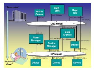
Nodebus Other Integration Products • Application Workstation provides integration to third party devices • Multiple Media • RS232 or RS485 • Ethernet • Multiple Protocols • Modbus • AB Data Highway • I/O Gate - DDE • Scaleable ValueBlocks AW50/70 Integrator (w/ Foxblocks) AB PLC or GE PLC or SCADA System DDE I/O Gate E-net I/A Series Fieldbus RS-232 or RS485 Fieldbus Module 762 Controllers SCADA System Modbus AB Data highway + DDE I/O Gate E