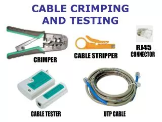
Cable Testing
Cable Testing. Introduction. Networking media is the backbone of network. Inferior quality of network cabling may cause network failures and unreliable performance. Copper, optical fiber, and wireless networking media all require testing to determine the quality.

Cable Testing
E N D
Presentation Transcript
Introduction • Networking media is the backbone of network. • Inferior quality of network cabling may cause network failures and unreliable performance. • Copper, optical fiber, and wireless networking media all require testing to determine the quality. • These tests involve certain electrical and mathematical concepts and terms, such as signal, wave, frequency, and noise.
Student Should understand the concepts of: • Sine waves and square waves. • Calculate exponents and logarithms. • Calculate decibels. • Time, frequency, and noise. • Digital and analog bandwidth. • Noise levels • Attenuation and impedance mismatch. • crosstalk, near-end crosstalk, far-end crosstalk, and power sum near-end crosstalk. • Grounding and wire twisting • copper cable tests defined in TIA/EIA-568-B. • Category 5 and Category 6 cable.
Waves…….. • A wave is energy traveling from one place to another. • It may be defined as any disturbance generated in any material, such as: • Throwing a stone in water • Sound (created by disturbance in air) • Electric supply at your house (electric impulses generated in conductor wire by providing a pressure/ force or voltage level.
Sine Waves They repeat the same pattern at regular intervals. They occur naturally and change regularly over time. No two adjacent points on a graph have the same value.
Square Waves They repeat the same pattern at regular intervals. They repeat the flat pattern on both the top and bottom of the wave. They do not continuously vary with time.
Signals • Signals in a network can be represented in two different ways. • Analog Signals • Digital Signals
Length Time Analog Signals • Is wavy • Has a continuously varying voltage versus time graph • Is typical of things in nature • Has been widely used in Telecommunications for over 100 years
Digital Signal • Digital signals have a square wave with instant transitions from low to high voltage states (0 to 1). • If voltage present then 1. • If no voltage then 0
Networks Use Digital Signaling • Bits are represented by either no voltage (0) or +3 to +6 Volts (1). • A Signal Reference Ground attached close to a computer’s digital circuits establishes the baseline for no voltage. • Bits must arrive at the destination undistorted in order to be properly interpreted. • What six things can distort a bit?
Decibels • The decibel (dB) is a measurement unit important in describing networking signals. The decibel is related to the exponents and logarithms. • Pfinal is the delivered power measured in Watts • Pfinal is the delivered power measured in Watts • Vfinal is the delivered voltage measured in Volts • Vreference is the original voltage measured in Volts
Noise in Time and Frequency • Noise is unwanted additions to the signal • Noise is unavoidable • Too much noise can corrupt a bit turning a binary 1 into a binary 0, or a 0 into a 1, thus destroying the message. • There are five kinds of noise: • NEXT A; Thermal Noise; Impulse/Reference Ground Noise; EMI/RFI; & NEXT B
Attenuation and Insertion Loss on Copper Media Attenuation is the loss of signal strength. The signal degrades or losses amplitude as it travels (propagates) along the medium • Loss of amplitude means that the receiving device can no longer distinguish a 1 bit from a 0 bit. • Attenuation is prevented by: • Not exceeding a medium’s distance requirement (100 meters for Cat 5 cable) • By using repeaters that “amplify” the signal
EMI/RFI Noise • EMI (Electromagnetic Interference) and RFI (Radio Frequency Interference) attack the quality of electrical signals on the cable. • Sources of EMI/RFI include: • Fluorescent lighting (EMI) • Electrical motors (EMI) • Radio systems (RFI)
Digital Signal EMI Distorted Signal EMI/RFI Noise Example • Source computer sends out a digital signal. • Along the path, the signal encounters EMI noise. • The digital signal and EMI combine to distort the signal.
EMI/RFI Noise • Two ways to prevent EMI/RFI Noise: • Through shielding the wires in the cable with a metal braid or foil. (Increases cost and diameter of the cable) • Through cancellation the wires are twisted together in pairs to provide self-shielding within the network media.
Canceling EMI/RFI Noise • UTP Cat 5 has eight wires twisted into four pairs. • In each pair, one wire is sending data and the other is receiving. • As the electrons flow down the wire, they create a small, circular magnetic field around the wire.
Canceling EMI/RFI Noise • Since the two wires are close together, their opposing magnetic fields cancel each other. • They also cancel out outside magnetic fields (EMI/RFI). • Twisting of the wires enhances cancellation
Types of Crosstalk NEXT computed as the ratio of voltage amplitude between the test signal and the crosstalk signal when measured from the same end of the link. Crosstalk is avoided Near-end crosstalk (NEXT) by using proper installation including: • Strict adherence to RJ-45 termination procedures • Using high quality twisted pair cabling
Types of Crosstalk Far-end crosstalk (FEXT) Due to attenuation, crosstalk occurring further away from the transmitter creates less noise on a cable than NEXT. This is called far-end crosstalk, or FEXT. The noise caused by FEXT still travels back to the source, but it is attenuated as it returns.
Types of Crosstalk Power sum near-end crosstalk (PSNEXT) Power Sum NEXT (PSNEXT) measures the cumulative effect of NEXT from all wire pairs in the cable. PSNEXT is computed for each wire pair based on the NEXT effects of the other three pairs. The combined effect of crosstalk from multiple simultaneous transmission sources can be very detrimental to the signal.
Timing Problems • Dispersion—similar to attenuation; is the broadening of a signal as it travels down the media. • Jitter—caused by unsynchronized clocking signals between source and destination. This means bits will arrive later or earlier than expected. • Latency—is the delay of a network signal caused by: • Time it takes a bit to travel to its destination • Devices the bit travels through
Collisions • Collisions occur in broadcast topologies where devices share access to the network media. • A collision happens when two devices attempt to communicate on the shared-medium at the same time. • Collisions destroy data requiring the source to retransmit. • The prevention of collisions will be discussed in more detail later in the semester.
New Standard • On June 20, 2002, the Category 6 (or Cat 6) addition to the TIA-568 standard was published. • This new standard specifies the original set of performance parameters that need to be tested for Ethernet cabling as well as the passing scores for each of these tests. • A quality cable tester is the Fluke DSP-LIA013 Channel/Traffic Adapter for Cat5e.