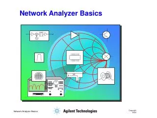

Network Basics and Elements
E N D
Presentation Transcript
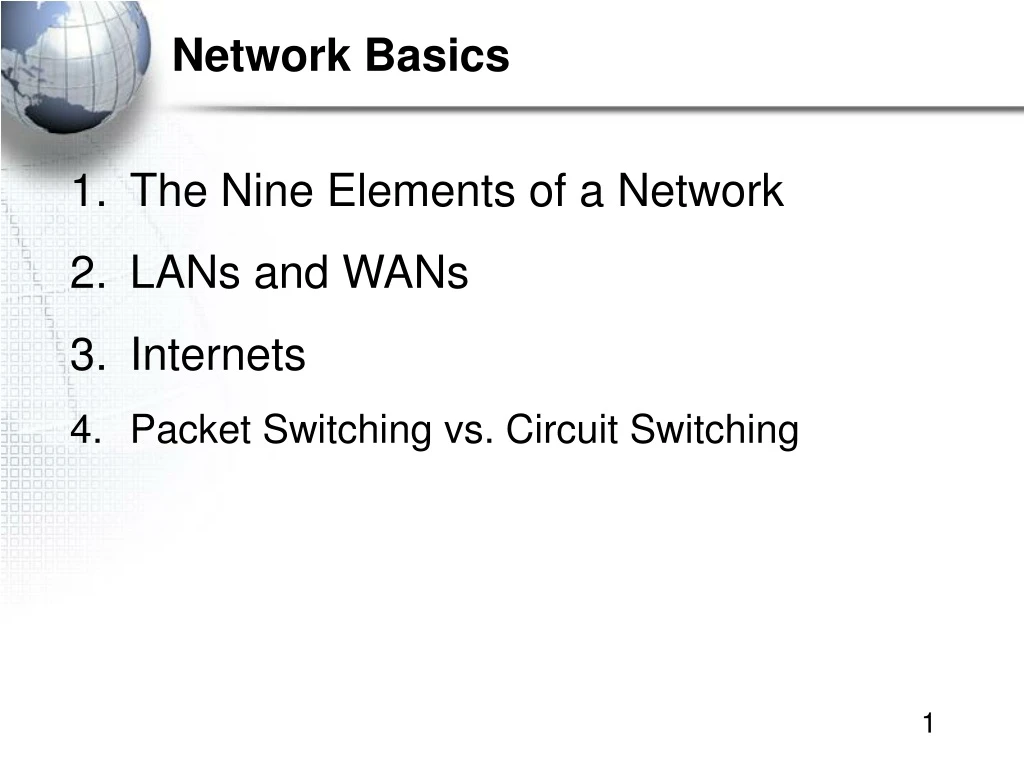
Network Basics • The Nine Elements of a Network • LANs and WANs • Internets • Packet Switching vs. Circuit Switching
1. The Nine Elements of a Network Although the idea of “network”is simple, you must understand the nine elements found in most networks
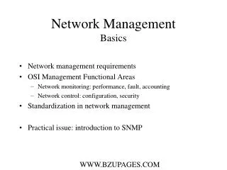
Figure 1-3: Elements of a Network Client Application Server Application Message (Frame) Switch 2 Access Line Client Computer Networks connect applications on different computers. Applications are all users care about Server Computer Switch 1 Switch 3 Trunk Line Mobile Client Outside World Wireless Access Point Router
Figure 1-3: Elements of a Network Client Application Server Application Message (Frame) Switch 2 Access Line Client Computer Networks connect computers: clients (fixed and mobile) and servers Server Computer Switch 1 Switch 3 Trunk Line Mobile Client Outside World Wireless Access Point Router
Figure 1-3: Elements of a Network Client Application Server Application Message (Frame) Data Link Client Computer Server Computer The path a frame takes is called its data link Computers (and routers) usually communicate by sending messages called frames Switch 1 Switch 3 Trunk Line Mobile Client Outside World Wireless Access Point Router
Figure 1-3: Elements of a Network Client Application Server Application Message (Frame) Frame to Sw1 Frame to Sw2 Frame To Sw3 Frame to Server Switch 2 Client Computer Server Computer Switch 1 Switch 3 Trunk Line Switches Forward Frames Sequentially Mobile Client Outside World Switch 4 Wireless Access Point Router
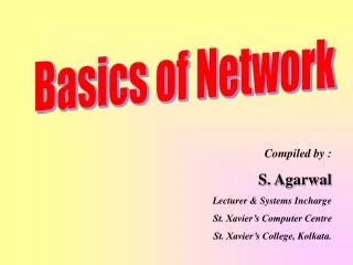
Switching Table PortHost 10 A1-44-D5-1F-AA-4C 13 B2-CD-13-5B-E4-65 15 C3-2D-55-3B-A9-4F 16 D4-47-55-C4-B6-F9 15 C3-2D-55-3B-A9-4F Figure 1-5: Ethernet Switch Operation C3- is out Port 15 D4-47-55-C4-B6-F9 Switch 2 Port 15 3 Frame to C3… Frame to C3… 1 C3-2D-55-3B-A9-4F A1-44-D5-1F-AA-4C B2-CD-13-5B-E4-65 Switch sends frame to C3- A1- sends a frame to C3-
Figure 1-3: Elements of a Network Small Switches (Stacked): Both sizes of switches are48 cm (19 inches) wide Large Switch
Figure 1-3: Elements of a Network Client Application Server Application Message (Frame) Switch 2 Access Line Client Computer Server Computer Wireless Access Points Connect Wireless Stations to Switches Switch 1 Switch 3 Trunk Line Mobile Client Outside World Switch 4 Wireless Access Point Router
Figure 1-3: Elements of a Network Client Application Server Application Message (Frame) Switch 2 Access Line Client Computer Server Computer Routers connect networks to the outside world; Treated just like computers in single networks Switch 1 Switch 3 Trunk Line Mobile Client Outside World Switch 4 Wireless Access Point Router
Figure 1-3: Elements of a Network Client Application Server Application Message (Frame) Access Line Switch 2 Client Computer Access Lines Connect Computers to Switches Server Computer Switch 1 Switch 3 Trunk Line Mobile Client Outside World Switch 4 Wireless Access Point Router
Figure 1-3: Elements of a Network Client Application Server Application Message (Frame) Switch 2 Access Line Client Computer Server Computer Trunk Lines Switch 1 Switch 3 Trunk Line Mobile Client Outside World Trunk Lines Connect Switches to Switches and Switches to Routers Switch 4 Wireless Access Point Router
Figure 1-4: Packet Switching and Multiplexing Breaking Communications into Small Messages is Called Packet Switching, even if the Messages are Frames AC AC Server Computer C AC Client Computer A AC AC BD AC Trunk Line Multiplexing Mixes the Messages of Multiple Conversations on a Trunk Line So Packet Switching Reduces the Cost of Trunk Lines BD Access Line BD BD Router D Mobile Client Computer B
First Bank of Paradise (FBP) • The book’s running case study • Composite mid-size bank in Hawaii • Banks are fairly “typical” firms, although they have stronger need for security • Warren Chun is the chief information officer (CIO) • Yvonne Champion is the network manager
First Bank of Paradise (FBP) • Annual Revenues: $4.5 Billion • Operations • 60 Branches • 375 ATMs (Automated Teller Machines) • Network • 700 Ethernet switches • 450 Routers
First Bank of Paradise (FBP) • Computers • 2,300 desktop and notebook user PCs • 130 Windows servers • 60 Unix servers • Information Systems Staff • 112 people
Characteristics LANs WANs Scope For transmission within a site. Campus, building, and SOHO (Small Office or Home Office) LANs For transmission between sites Cost per bit Transmitted Low High Typical Speed Unshared 100 Mbps to a gigabit per second to each desktop. Even faster trunk line speeds. Shared 128 kbps to several megabits per second trunk line speeds Figure 1-8: LANs Versus WANs
Choices Unlimited Only those offered by carrier Figure 1-8: LANs Versus WANs Characteristics LANs WANs Management On own premises, so firm builds and manages its own LAN or outsources the Work Must use a carrier with rights of way for transmission in public Area. Carrier handles most work but Charges a high price.
Figure 1-9: Local Area Network (LAN) in a Large Building Multi-floor Office Building The bank has multiple LANs—one at each site
Figure 1-9: Local Area Network (LAN) in a Large Building Wall Jack Workgroup Switch 2 Client Server Workgroup Switch 1 Wall Jack To WAN Core Switch Router Frames from the client to the server go through Workgroup Switch 2, through the Core Switch, through Workgroup Switch 1, and then to the server
Figure 1-10: Workgroup Switch(19 inches / 48 cm Wide) 48 cm (19 in.) Workgroup Switch with 16 ports Wire cord going out to a computer or to another switch
Figure 1-7: The First Bank of Paradise’s Wide Area Networks (WANs) Frame Relay Network Branch Office North Shore Operations OC3 Private Leased Line T3 Bank has multiple facilities connected by multiple WANs T3 Headquarters
Router Router Figure 1-11: Internets • Single LANs Versus Internets • In single networks (LANs and WANs), all devices connect to one another by switches—our focus so far. • In contrast, an internet is a group of networks connected by routers so that any application on any host on any single network can communicate with any application on any other host on any other network in the internet. Application Application WAN LAN LAN
PDA (Host) Client PC (Host) VoIP Phone (Host) Server (Host) Cellphone (Host) Figure 1-11: Internets • Internet Components • All computers in an internet are called hosts • Servers, clients, PDAs, cellphones, etc. Internet Cat
Figure 1-11: Internets • Hosts Have Two Addresses • IP Address • This is the host’s official address on its internet • 32 bits long • Expressed for people in dotted decimal notation (e.g., 128.171.17.13) • Single-Network Addresses • This is the host’s address on its single network • Ethernet addresses, for instance, are 48 bits long • Expressed in hexadecimal notation (e.g., AF-23-9B-E8-67-47)
Figure 1-11: Internets • Networks are connected by devices called routers • Switches provide connections within networks, while routers provide connections between networks in an internet. • Frames and Packets • In single networks, message are called frames • In internets, messages are called packets
Figure 1-11: Internets • Packets are carried within frames • One packet is transmitted from the source host to the destination host • Its IP destination address is that of the destination host • In each network, the packet is carried in (encapsulated in) a frame (Figure 1-12) • If there are N networks between the source and destination hosts, there will be one packet and N networks between the source and destination hosts, there will be one packet and N frames for a transmission
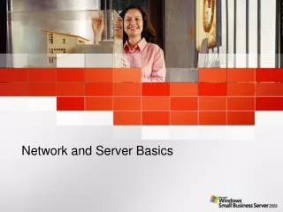
Figure 1-12: Internet with Three Networks Host A R1 Packet Network X A packet goes all the way across the internet; It’s path is its route Network Y Route A-B Network Z R2 Host B
Messages in single networks (LANs or WANs) are called frames Message in internets are called packets Travel from the source host to the destination host across the entire internet Within a single network, the packet is encapsulated in (carried in) the network’s frame Figure 1-12: Internet with Three Networks Package (Packet) Truck (frame) Packet Frame
Figure 1-12: Internet with Three Networks In Network X, the Packet is Placed in Frame X Frame X Details in Network X Packet Switch Host A 10.0.0.23 AB-23-D1-A8-34-DD Switch Server Host Data link A-R1 A data Link is a frame’s path through its single network Switch X1 A route is a packet’s path through the internet Mobile Client Host Switch X2 Router R1 D6-EE-92-5F-C1-56 Route A-B Network X
Figure 1-12: Internet with Three Networks Details in Network Y To Network X Route A-B Router R1 Frame Y Data Link R1-R2 Packet Router R2 AF-3B-E7-39-12-B5 Network Y To Network Z
Figure 1-12: Internet with Three Networks Details in Network Z Frame Z Packet Data Link R2-B Switch Z1 Switch Host B www.pukanui.com 1.3.45.111 55-6B-CC-D4-A7-56 Router R2 Switch Z2 Switch Router Mobile Client Host Mobile Client Computer Network Z
Figure 1-12: Internet with Three Networks • In this internet with three networks, in a transmission, • There is one packet • There are three frames (one in each network) • If a packet in an internet must pass through 10 networks, • How many packets will be sent? • How many frames must carry the packet?
Spelled in lowercase, “internet” is any internet Spelled in uppercase, “Internet” is the global Internet Figure 1-12: Internet with Three Networks
Figure 1-13: Converting IP Addresses into Dotted Decimal Notation IP Address (32 bits long) 10000000101010110001000100001101 Divided into 4 bytes. These are segments. 10000000 10101011 00010001 00001101 Convert each byte to decimal (result will be between 0 and 255)* 128 171 17 13 Dotted decimal notation (4 segments separated by dots) 128.171.17.13 *The conversion process is described in the Hands On section at the end of the chapter.
Figure 1-14: The Internet, internets, Intranets, and Extranets • The Global Internet • As noted earlier, • Spelled with a lowercase i, internet means any internet • Spelled with a uppercase I, Internet means the global Internet
Figure 1-14: The Internet, internets, Intranets, and Extranets • The Internet (Figure 1-18) • Host computers • Internet service providers (ISPs) • Required to access the Internet • Carry your packets across the Internet • Collect money to pay for the Internet • The Internet backbone consists of many ISPs • ISPs interconnect at Network access points (NAPs) to exchange cross-ISP traffic
Figure 1-17: The Internet Webserver Host Computer User PC Host Computer Internet Backbone (Multiple ISP Carriers) Access Line Access Line Router NAP NAP ISP ISP ISP NAP ISP Webserver’s Internet Service Provider User PC’s Internet Service Provider NAP = Network Access Point
Figure 1-17: The Internet User PC Host Computer Webserver Host Internet Backbone (Multiple ISP Carriers) Access Line Access Line Router NAP NAP ISP ISP ISP NAP ISP Webserver’s Internet Service Provider User PC’s Internet Service Provider NAP = Network Access Point
Figure 1-18: Subnets in an Internet LAN 2 LAN 1 LAN Subnet 60.4.3.x Router R1 LAN Subnet 10.1.x.x Router R4 LAN Subnet 60.4.15.x LAN Subnet 10.2.x.x LAN Subnet 60.4.7.x WAN Subnet 123.x.x.x LAN Subnet 10.3.x.x LAN Subnet 60.4.131.x Router R3 Router R2 Note: Subnets are single networks (collections of switches, transmission lines)
Figure 1-19: Terminology Differences for Single-Network and Internet Professionals By Single-Network Professionals By Internet Professionals Single Networks Are Called Networks Subnets Internets Are Called Internets Networks • In this book, to avoid confusion, • we will call internets “internets” • and subnets “single networks”
Figure 1-14: The Internet, internets, Intranets, and Extranets • Intranets • An intranet is an internal internet for use within an organization • Based on the TCP/IP standards created for the Internet “Intra” means “within”
Figure 1-14: The Internet, internets, Intranets, and Extranets • Extranets • To connect multiple firms • Only some computers from each firm are on the extranet • Use TCP/IP standards “Extra” means “outside”
Figure 1-14: The Internet, internets, Intranets, and Extranets • Intranets, Extranets, and the Internet • Confusingly, both intranets and extranets can use the Internet for some of their transmission capacity
Figure 1-16: Small Router for a Branch Office (19 inches / 48 cm Wide)
Figure 1-20: IP Address Management • Every Host Must Have a Unique IP address • Server hosts are given static IP addresses (unchanging) • Clients get dynamic (temporary) IP addresses that may be different each time they use an internet • Dynamic Host Configuration Protocol (DHCP) • Clients get these dynamic IP addresses from Dynamic Host Configuration Protocol (DHCP) servers
Figure 1-21: Dynamic Host Configuration Protocol (DHCP) Pool of IP Addresses Client PC A3-4E-CD-59-28-7F DHCP Server DHCP Request Message: “My 48-bit Ethernet address is A3-4E-CD-59-28-7F”. Please give me a 32-bit IP address.”