Download
1 / 50
680 likes | 1.51k Vues
OPTO ISOLATOR. We know from our tutorials about Transformers that they can not only provide a step-down (or step-up) voltage, but they also provide “electrical isolation” between the higher voltage on the primary side and the lower voltage on the secondary side.

E N D
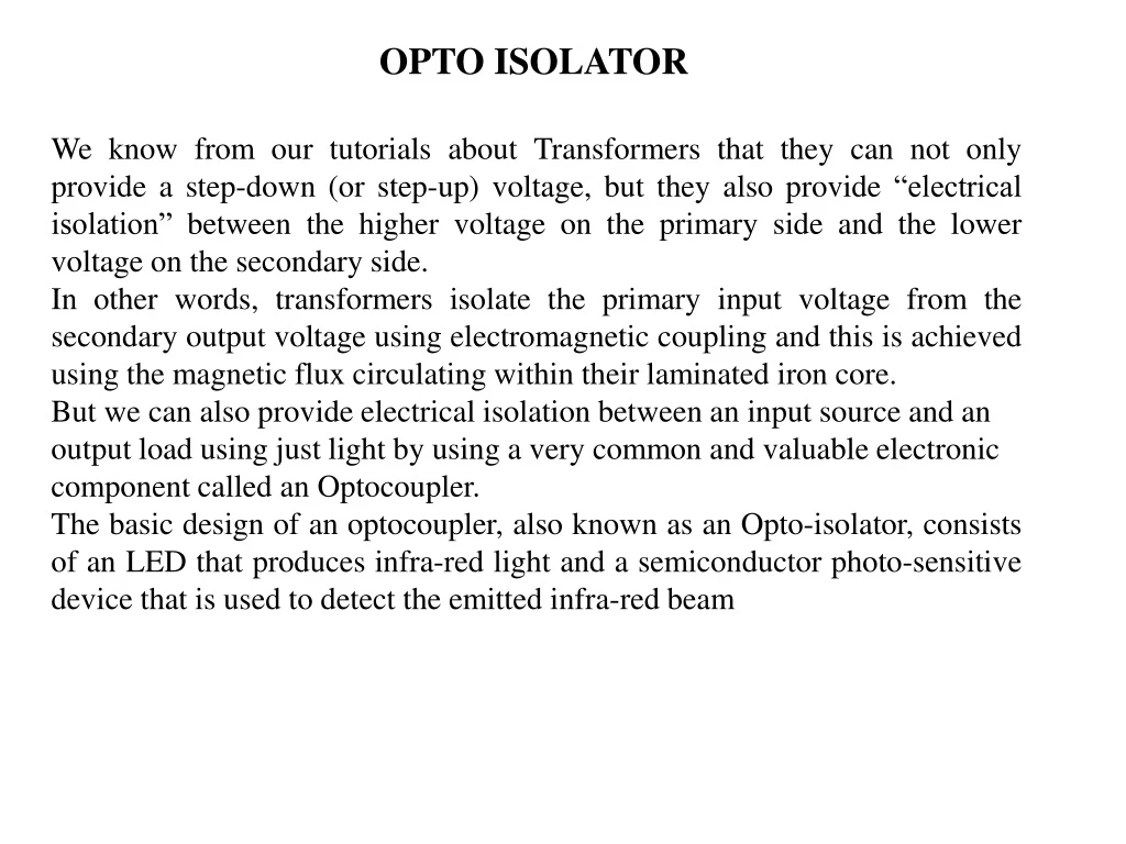
OPTO ISOLATOR We know from our tutorials about Transformers that they can not only provide a step-down (or step-up) voltage, but they also provide “electrical isolation” between the higher voltage on the primary side and the lower voltage on the secondary side. In other words, transformers isolate the primary input voltage from the secondary output voltage using electromagnetic coupling and this is achieved using the magnetic flux circulating within their laminated iron core. • But we can also provide electrical isolation between an input source and an output load using just light by using a very common and valuable electronic component called an Optocoupler. • The basic design of an optocoupler, also known as an Opto-isolator, consists of an LED that produces infra-red light and a semiconductor photo-sensitive device that is used to detect the emitted infra-red beam
OPTO ISOLATOR-TYPES • Optocouplers are available in four general types, each one having an infra-red LED source but with different photo-sensitive devices. The four optocouplers are called the: Photo-transistor, Photo-darlington, Photo-SCR and Photo-triac as shown below. The photo-transistor and photo-darlington devices are mainly for use in DC circuits while the photo-SCR and photo-triac allow AC powered circuits to be controlled.
PHOTOTRANSISTOR-OPTO ISOLATOR • The opto-isolator consists of an LED and a phototransistor within a single package. • When zero volts (logical 0) is applied to the input of theopto-isolator, the LED is • turned off. The phototransistor receives no lightand is also turned off. The pull-up • resistor R therefore produces an outputvoltage of approximately VCC. • If a positive voltage (logical 1) is applied to theinput of the opto-isolator, the LED • will be illuminated, causing the phototransistorto turn on. This will pull down the • output voltage to close to zerovolts. • Thus, the opto-isolator acts as a logical inverter. The important aspectof the operation of this arrangement is that there is no electrical connectionbetween the input and the output – they are linked only by light. • Typicaldevices produce several kilovolts of electrical isolation. Both the input Andthe output lines of a system can be protected in this way. • Since there is no direct electrical connection between the input and output of • an optocoupler, electrical isolation up to 10kV is achieved.
In the upper image the internal construction is shown inside a Photo-transistor Optocoupler. The Transistor type can be anything whether PNP or NPN. Photo-Transistor can be further of two types depending on the output pin availability. On the second image on the left, there is additional pin out which is internally connected with transistor’s base. This pin 6 is used to control the sensitivity of the photo-transistor. Often the pin is used to connect with ground or negative using a high value resistor. In this configuration, false triggering due to noise or electrical transients can be controlled effectively. Also, before using Photo-transistor based optocoupler, the user must know the maximum rating of the transistor. PC816, PC817, LTV817, K847PH are few widely used photo-transistor based optocoupler. Photo – Transistor based opto-coupler is used in DC circuit related isolation.
PHOTO-DARLINGTON TRANSISTOR OPTOCOUPLER In the upper image there are two types of symbol, internal construction of Photo-Darlington based opto-coupler is shown. Darlington Transistor is two transistor pair, where one transistor controls other transistor base. In this configuration the Darlington Transistor provide high gain ability. As usual the LED emits infrared led and controls the base of the pair transistor. This type of opto-coupler also used in DC circuit related area for the isolation. The 6th pin which is internally connected to the base of the transistor, used to control the sensitivity of the transistor as discussed previously in photo-transistor description. 4N32, 4N33, H21B1, H21B2, H21B3 are few photo-Darlington based opto-coupler example.
PHOTO-TRIAC OPTOCOUPLER In the upper image the internal construction or the TRIAC based opto-coupler is shown. TRIAC is mainly used where AC based control or switching is needed. The led can be controlled using DC, and the TRIAC used to control AC. Opto-coupler provide excellent isolation in this case too. Here is one Triac Application. The photo-TRIAC based opto-coupler examples areIL420, 4N35 etc are example of TRIAC based opto-coupler.
PHOTO-SCR BASED OPTOCOUPLER SCR stand for Silicon controlled rectifier, SCR also referred as Thyristor. In the upper image a Photo-SCR based opto-coupler’s internal construction is shown. Same as like other opto-coupler the LED emit Infrared. The SCR is controlled by the intensity of the LED. Photo-SCR based Opto-coupler used in AC related circuitry. Learn more about Thyristor here. Few Examples of photo-SCR based opto-couplers are:- MOC3071, IL400, MOC3072 etc.
Why relays? • As the name suggests, many sensors are incredibly sensitive pieces of electronic equipment and produce only small electric currents. • But often we need them to drive bigger pieces of apparatus that use bigger currents. • Relays bridge the gap, making it possible for small currents to activate larger ones. That means relays can work either as switches (turning things on and off) or as amplifiers (converting small currents into larger ones).
RELAY What are relays? • A relay is an electromagnetic switch operated by a relatively small electric current that can turn on or off a much larger electric current.
Normaly Closed Relay->Relay not energized->Contact is closed Note->Normal state is the non-energized state
How relays work? • When power flows through the first circuit (1), it activates the electromagnet (brown), generating a magnetic field (blue) that attracts a contact (red) and activates the second circuit (2). • When the power is switched off, a spring pulls the contact back up to its original position, switching the second circuit off again. • This is an example of a "normally open" (NO) relay: the contacts in the second circuit are not connected by default, and switch on only when a current flows through the magnet. • Other relays are "normally closed" (NC; the contacts are connected so a current flows through them by default) and switch off only when the magnet is activated, pulling or pushing the contacts apart. Normally open relays are the most common.
Relay Linking two circuits together • The input circuit (blue loop) is switched off and no current flows through it until something (either a sensor or a switch closing) turns it on. The output circuit (red loop) is also switched off. • When a small current flows in the input circuit, it activates the electromagnet (shown here as a dark blue coil), which produces a magnetic field all around it. • The energized electromagnet pulls the metal bar in the output circuit toward it, closing the switch and allowing a much bigger current to flow through the output circuit. • The output circuit operates a high-current appliance such as a lamp or an electric motor.
Different types of relay • SPST-> Single Pole Single Throw • SPDT-> Single Pole Double Throw • DPST-> Double Pole Single Throw • DPDT-> Double Pole Double Throw
Relays in practice • Suppose you want to build an electronically operated cooling system that switches a fan on or off as your room temperature changes. You could use some kind of electronic thermometer circuit to sense the temperature, but it would produce only small electric currents—far too tiny to power the electric motor in a great big fan. Instead, you could connect the thermometer circuit to the input circuit of a relay. When a small current flows in this circuit, the relay will activate its output circuit, allowing a much bigger current to flow and turning on the fan. • Relays don't always turn things on; sometimes they very helpfully turn things off instead. In power plant equipment and electricity transmission lines, for example, you'll find protective relays that trip when faults occur to prevent damage from things like current surges. Electromagnetic relays similar to the ones described above were once widely used for this purpose. These days, electronic relays based on integrated circuits do the same job instead; they measure the voltage or current in a circuit and take action automatically if it exceeds a preset limit.
Data Converters Why? • Effect of noise more in Analog s/m compared to digital s/m • So Analog->Digital->Analog A to D converter D to A converter
A/D->Sampling • Sampling an analog signal -> Take the instantaneous reading of the analog signal’s magnitude and convert this into a digital form. • Sampling at what rate?->Nyquist rate • Nyquist rate-> sampling rate must be greater thantwice the highest frequency present in the signal being sampled so that none of the information in the signal is lost by sampling. • A range of converters is available, each providing conversion to a particular resolution. This determines the number of steps or quantization levels that are used. An n-bit converter produces or accepts an n-bit parallel word and uses 2n discrete steps. Thus, an 8-bit converter uses 256 levels and a 10-bit converter uses 1024 levels. It should be noted that the resolution of a converter may be considerably greater than its accuracy.
Types of ADC • SAR ADC • Sigma Delta ADC • Dual Slope ADC • Flash ADC • Flash ADC ->applications which require high speed and low resolution. • faster due to its parallel architecture and hence it is also known as parallel ADC.
Flash ADC VIN=6 V VREF=7 V D7 10K 0.49 V =6.99V D6 =5.99V 10K 8.5 V =5.99V D5 10K =4.99V 8.5 V =4.99V D4 10K =3.99V 8.5 V =3.99V D3 =2.99V 10K 8.5 V =2.99V D2 =1.99V 10K 8.5 V =1.99V =0.99V D1 10K 8.5 V =0.99V
Flash ADC->Op Amp IC Pin diagram of IC LM324 –QUAD OP-AMP
Flash ADC->Priority Encoder • For example an input voltage ≥ 2 and <3 say 2.5V will give the out as • 010.
Flash ADC->Other IC’s used IC 7408 –QUAD 2 input AND gate IC 7432 –QUAD 2 input OR gate IC 7432 –QUAD 2 input OR gate
DAC • Digital to Analog Converter (DAC) is a device that transforms digital data into an analog signal. • According to the Nyquist-Shannon sampling theorem, any sampled data can be reconstructed perfectly with bandwidth and Nyquist criteria. • A DAC can reconstruct sampled data into an analog signal with precision. The digital data may be produced from a microprocessor, Application Specific Integrated Circuit (ASIC), or Field Programmable Gate Array (FPGA), but ultimately the data requires the conversion to an analog signal in order to interact with the real world. • TYPES • Weighted resistor or Resistor Divider • R – 2R Ladder type
DAC using Weighted Resistors method The basic operation of DAC is the ability to add inputs that will ultimately correspond to the contributions of the various bits of the digital input. In the voltage domain, that is if the input signals are voltages, the addition of the binary bits can be achieved using the inverting summing amplifier shown in the below figure. IMPLEMENT USING SWITCHES + ->Implement addition as adding of currents 1101-> 1*8+1*4+0*2+1*1 How? By having voltage source in addition to the resistors used And adding using opamp inverting summing amplifier IMPLEMENT USING RESISTORS
In the voltage domain, that is if the input signals are voltages, the addition of the binary bits can be achieved using the inverting summing amplifier shown in the above figure. The input resistors of the op-amp have their resistance values weighted in a binary format. When the receiving binary 1 the switch connects the resistor to the reference voltage. When the logic circuit receives binary 0, the switch connects the resistor to ground. All the digital input bits are simultaneously applied to the DAC. The DAC generates analog output voltage corresponding to the given digital data signal. For the DAC the given digital voltage is b3 b2 b1 b0 where each bit is a binary value (0 or 1). The output voltage produced at output side is V0=R0/R (b3+b2/2+b1/4+b0/8) Vref As the number of bits is increasing in the digital input voltage, the range of the resistor values becomes large and accordingly, the accuracy becomes poor.
STAIRCASE WAVE IMPLEMENTATION->DAC using IC74190 and op amp IC74190
FLYBACK DIODE
a b c d e f g
a b c d e f g
Current Limiting Resistors Common Anode a b c d e f g
Current Limiting Resistors Common Anode a b c d e f g
V2 V1 R2 R1