Download
1 / 21
210 likes | 355 Vues
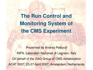
The Run Control and Monitoring System of the CMS Experiment. Presented by Andrea Petrucci INFN, Laboratori Nazionali di Legnaro, Italy On behalf of the DAQ Group of CMS collaboration ACAT 2007, 23-27 April 2007, Amsterdam, Netherlands. Outline. R un C ontrol and M onitor S ystem :

E N D
The Run Control and Monitoring System of the CMS Experiment Presented by Andrea Petrucci INFN, Laboratori Nazionali di Legnaro, Italy On behalf of the DAQ Group of CMS collaboration ACAT 2007, 23-27 April 2007, Amsterdam, Netherlands
Outline RunControl and Monitor System : • Architecture • LogicalLayer • Services • Components • Technologies • At the Magnet Test and Cosmic Challenge (MTCC) • Control structure • Operation • Components • Results • GRICC Project Andrea Petrucci - LNL-INFN
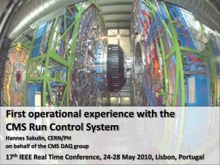
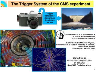
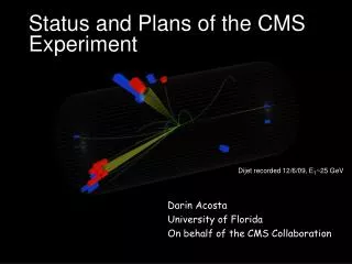
What is CMS? The Compact Muon Solenoid (CMS) experiment is one of two large general-purpose particle physics detectors being built on the proton-proton Large Hadron Collider (LHC) at CERN in Switzerland. The main goals of the experiment are: • to explore physics at the TeV scale • to discover the Higgs boson • to look for evidence of physics beyond the standard model • to be able to study aspects of heavy ion collisions Andrea Petrucci - LNL-INFN
Run Control and Monitor System • The RunControl and Monitor System (RCMS) is responsible for controlling and monitoring the CMS experiment during the data taking. • RCMS views the experiment as a set of partition, where a partition is a grouping of entities that can be operated independently. • Main operations are configuration, monitoring, error handling, logging and synchronization with other subsystems. Andrea Petrucci - LNL-INFN
CMS Data Acquisition • Baseline DAQ Configuration • 512 inputs • 2024 outputs • Control and Monitor requirements • O(104 ) distributed Objects to • control • configure • monitor • On-line diagnostics • Interactive system Andrea Petrucci - LNL-INFN
Run Control and Monitor System TheSOAP protocol and the Web Services have been adopted as the main means for communication . The online process environment is XDAQ, a C++ framework for a distributed Data Acquisition System. RCMS is integrated in the CMS On-line system : • It controls the “DAQ component” • Data transport • Event processing • It monitors the “Detector Control System” DCS • manages the slow controls of the whole experiment. Andrea Petrucci - LNL-INFN
RCMS Logical Structure • A Session is the allocationofthe hardware and software of a CMS partitionneededtoperformdata-taking. • Multiple Sessions may coexist and operate concurrently. • EachSessionisassociatedwith a Top Function Manager, thatcoordinatesall the actions. Services Top Services Services Sub-Detector Sub-Detector Sub-Detector Sub-Detector Sub-Detector Sub-Detector DAQ Resources Andrea Petrucci - LNL-INFN
RCMS Services • SECURITY SERVICE • login and user account management; • RESOURCE SERVICE (RS) • informationabout DAQ resources and partitions; • INFORMATIONAND MONITOR SERVICE (IMS) • Collectsmessages and monitor data; distributesthemto the subscribers; • JOB CONTROL • Starts, monitors and stops the softwareelementsof RCMS, including the DAQ components; Andrea Petrucci - LNL-INFN
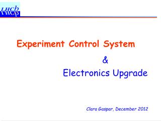
Resources Function Manager Event Processor FSM Engine Input Handler Resource Proxy Function Manager Monitor Flow The purpose of a Function Manager (FM) is to control a set of resources. Control Flow • Input Handler: It handles all the input events of the FM (GUIs or other FMs, errors, states, logs and monitor messages) • Event Processor: It handles all the incoming message and decide where to send them. It has processing capability • Finite State Machine (FSM): The behavior of the FM is driven by a FSM. • Resource Proxy: It handles all the outgoing connections with the resources. State Flow Error Flow Customizable Andrea Petrucci - LNL-INFN
RS DB Resource Service The Resource Service (RS) stores the process configuration of the On-line System. RS Manager tool DAQ Configurator RS API Andrea Petrucci - LNL-INFN
Display System Log Collector Message System Access via TCP Log Collector Publish Subscriber System … RCMS applications and XDAQ applications • Collects log information from log4j compliant applications (i.e. on-line process). Access via JDBC Storage System • Send log information directly to a Display System (Chainsaw) . Relational DB Oracle,MySQL • Stores log information in a database and visualizes them (LogDBViewer) . • Distributes/publishes log information through a message system (Java Message Service). Andrea Petrucci - LNL-INFN
DAQ Configurator Configuration JobControl Process Control RCMS main components Log Messages RS DB GCK DB RunInfo DB Log DB Hwcfg DB RS API RunInfo API Hwcfg API Config data Conditions data Config data RS ManagerManager/Editor Function Manager Framework Firefox JSP/Ajax GUI Process Config Log Collector WebApp Commands Notifications Chainsaw Log Viewer User Interface RCMS Andrea Petrucci - LNL-INFN
RCMS Technologies • Technologies and tools: • Web Applications,Java Servlets (Apache Tomcat) • WebService (Axis, WSDL, SOAP) • Web Tecnologies (Ajax,JSP) • Databases • Oracle • MySQL Andrea Petrucci - LNL-INFN
Magnet Test and Cosmic Challenge The Magnet Test and Cosmic Challenge (MTCC) is a milestone of the CMS experiment, it completes the commissioning of the magnet system (coil & yoke) before its lowering into the cavern. • The main goals of the Cosmic Challenge were: • Test Muon alignment systems. • Commission the several sub-detectors (Drift Tubes - DT, Hadron Calorimeter – HCAL, Tracker, etc.) and Cosmic Trigger. • demonstrate cosmic ray reconstruction with multiple sub-detectors. Scale MTCC versus CMS Data Sources: 20 out of 600 3% Filter Nodes: 14 out of 2000 0.3% Trigger rate: 100 Hz out of 100 kHz 0.1% Event size: 200 kB out of 1 MB 20% Andrea Petrucci - LNL-INFN
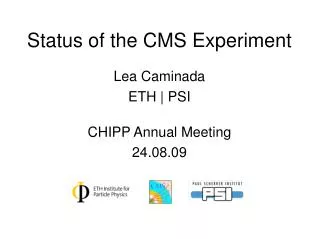
FMs Control Structure at MTCC I & II User interaction with Web Browser connected to Level 0 FM. Web Browser (GUI) TOP Level 0 FM is entry point to Run Control System. Level 0 FM ECAL LTC RPC DT Level 1 FM interface to the Level 0 FM and have to implement a standard set of inputs and states. CSC DAQ TRK HCAL Level 1 FM FB RB FF FEC FED Level 2 FMs are sub-system specific custom implementations. Level 2 FM Resources are on-line system components Resources Andrea Petrucci - LNL-INFN
RCMS at MTCC I & II Top DAQ • RCMS Operation Scenario • Sub-system function managers were written using the RCMS software • The run configuration was communicated via a global configuration key • The Run Info DB was used to store end-of-run summary information and status information about the run. • It also contained the schema to generate Run Numbers and Run Sequence Numbers. LTC CSC RPC DT ECAL HCAL TRK Andrea Petrucci - LNL-INFN
LOG DB Top DAQ RCMS Components at MTCC I & II DAQ RS Collector Collector global key Global Configuration Keys LTC-Trg LTC-Trg RS Top RS Collector CSC EMU RS Collector RPC RPC RS Collector DT DT RS Collector ECAL ECAL RS Collector global key HCAL HCAL RS local key Collector configuration logmessage TRK TRK RS Collector Andrea Petrucci - LNL-INFN
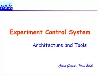
MTCC Data taking Andrea Petrucci - LNL-INFN
MTCC result • RCMS software was stable. • Separation of Subsystem installations worked well. • Recorded ~ 160 M events on a period of one month Andrea Petrucci - LNL-INFN
RCMS and GRIDCC The CMS RCMS is one of the main applications for the GRIDCC project . What is GRIDCC ? The Grid enabled Remote Instrumentation withDistributed Control and Computation (GRIDCC) is a projectfunded by the European community, aimed to provide access to and control of distributed complex instrumentation. • It is a project of 3-years and started in September 2004 • Web site: www.gridcc.org The RCMS software is the core of the Instrument Element of the GRIDCC. Andrea Petrucci - LNL-INFN
Thankyouforyourattention. • AnyQuestions? Andrea Petrucci - LNL-INFN