Download
1 / 34
340 likes | 524 Vues
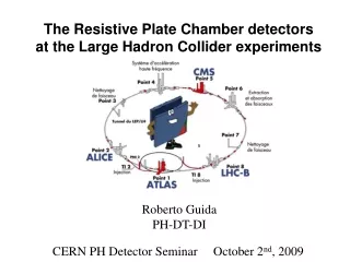
The Resistive Plate Chamber system for the CMS experiment. M. Abbrescia on behalf of the CMS/RPC group. IEEE/NSS 2005. Outline of the talk. Historical introduction The system: goals and design Construction and Quality Control Installation and Commissioning Dedicated R&D and open issues

E N D
The Resistive Plate Chamber system for the CMS experiment M. Abbrescia on behalf of the CMS/RPC group IEEE/NSS 2005
Outline of the talk • Historical introduction • The system: goals and design • Construction and Quality Control • Installation and Commissioning • Dedicated R&D and open issues • Conclusions M. Abbrescia Bari University and INFN IEEE/NSS 2005
The long road to CMS/RPC • The CMS/RPC project was originated by a small group of physicists from Bari (Italy) • During a meeting in Salzburg in 1992, interest was expressed to join CMS and to take part to the dedicated trigger system (Warsaw, Helsinki) • An intense R&D was needed to adapt the characteristics of RPCs to the hostile environment foreseen in CMS (1993-2005…). Colleagues from Pavia joined the effort. M. Abbrescia Bari University and INFN IEEE/NSS 2005
The long road to CMS/RPC (2) • During 1994-1995 some korean, chinese and, later, pakistan universities expressed interest in this project →Endcap • These groups had little experience in detector physics, but RPCs were considered an item easy to approach and suitable to develop local expertise in gaseous detectors → technology transfer • Also Sofia University, INRNE (Bulgaria) and, recently, Naples have joined the collaboration and are actively involved in the project • The CMS CERN group is now contributing to the assembly and test of forward chambers
Barrel: Bari, Napoli, Pavia, Sofia University, Sofia INRNE, Peking University Forward: Seoul (KODEL), Peking University, PAEC&Islamabad University , CERN, ITALY Trigger: Helsinki, Warsaw The collaboration … now
The detector • Main characteristics of the RPCs used in CMS: • Bakelite thickness: 2 mm • Bakelite bulk resistivity : 2-3 1010cm • Gap width: 2 mm • Operating voltage: 9-10 kV Gas mixture 95.5 Freon 3.5 Isob 0.3 SF6 + RH 50% Number of gaps: 2 Other experiments have decided to use different configurations: single gap in ATLAS, streamer mode and multi-gap in ALICE
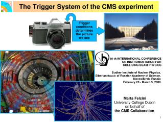
…A not easy task • CMS will be based on • “A very good redundant muon system” • (Technical Proposal, • CERN-LHCC 94-28, 15 Dec. 1999) • The first level muon trigger should guarantee: • Complete coverage of the solid angle • Robustness: maximal use of available information • Speed: decision time of the order of 1 ms • (Letter of intent • CERN-LHCC 92-3 1 Oct. 1992) CMS muon trigger 2 complementary and independent systems RPC : fast dedicated trigger detectors DT + CSC: wire chambers for precise muon pT measurement For the CMS muon system see the talk by A. Sharma
The requirements … • Physics requirements for the RPC system • muon identification • bunch crossing assignment (25 ns spaced b. x.) • cut on the muon pt Chamber Requirements Efficiency > 95 % Time resolution < 3 ns Cluster size < 2 strips Operational plateau > 300 V • CMS environmental conditions: • very good timing: 25 ns b.x. • long term operation: >10 years • neutron and gamma irradiation (up to 1 Gy) • expected maximum rate: ~100 Hz/cm2
RPCs in the CMS experiment • Barrel, a few numbers: • 5 Wheels • 12 sectors per wheel • 6 RPC station/sector • 8/7 chamber per sector • Total: 480 chambers • 2500 m2 surface • 50.000 electr. Chann. RPCs RPCs are used as muon trigger both in barrel and endcap
Design of the chambers Chamber dimension 120 RB1: 2 m 120 RB2: 2.5 m 120 RB3: 1.5 m 120 RB4: (1.5 2.5) m 2.5 m Chamber rectangular in the barrel Chambers trapezoidal in the endcaps, made of 3 independent Single Gap (SG)
RPC Barrel production & test sites GT Single gap Double gap Pavia ISR (CERN) Sofia Bari GT HT ChamberassemblingSites Chambertest Sites 120 RB1 at HT & GT 240 RB2 and RB4 at GT 120 RB3 in Sofia (& Bari) RB1 in Pavia RB2 & RB4 in Bari RB3 in Sofia (& Bari)
Flow of components (endcap) RPC trigger RE 1 assy & test Install & commission Bakelite Electronics Etc… Procurement Strips,panels etc RE 2 and 3 assy & test Gas gaps Assy & test … a round trip of 20 thousand km
Quality Control and Quality Assurance Quality Control – Define Specifications Quality Assurance – Meet Specifications … A learning process
Quality Control of Single Gaps (GT) SG assembled by GT Gas leakage test Control the gap “bubbles” in 30 s Overpressure test Reach an inside overpressure of 20 mbar: check if spacers or frame detach GT connects the HV wire ... The SG type (Right/Left) is assigned Bring the SG at 9500V and measure the current: reject if I > 5 A
Overview of SG rejections % # SG 2003 2005 2004 2002 % Accepted/to install = 87 % Note: here and in the following, some spares are accounted for # SG 2004 2005 2002 2003
Quality Control for Double Gaps 2 SG validated by previous step SG coupling Gas leakage test DG assembled by GT Check the gap “bubbles” in 30 s Bring the DG at 9500V and measure the current: reject if I > 5 A per single gap
Oververview of DG rejections So far 77 % of the needed DGs have been accepted % # DG # DG 2003 2004 2005
Quality Control for Chambers Production sites (HT-GT-SOFIA): quality control Test sites (Bari-Pavia-Sofia): study of chamber performance with cosmic rays ISR: long term current stability
Prod. Overview (barrel) Single Gaps: 2395 fully tested 87 % of needed have been accepted. End of production: December 05. Double Gaps: 922 fully tested77 % of needed have been accepted. End of production: February 06. Chambers 401 have been assembled 75 % of total production
Cosmics telescopes at test sites Sofia Pavia Bari ISR (Endcap)
Chamber efficiency Distribution of max. efficiency HV distribution at 95 % of max efficiency Efficiency in single/double gap
Noise, current and cluster size Counting Rate (High rates are due to a single noisy channel) Current distribution Cluster size
Commissioning at ISR • Final dressing • Final cooling, HV connectors, temperature sensors • Detector control • Up to 30 chambers can be tested at same time • Gas leak • Threshold setting and reading • Current vs. HV • Long stability test (15-20 days @ 9200 V) • Gas input overpressure test (since march) • Performance • 15 chambers can be tested at same time • Single rate (hits count.) vs. HV • Noise rate (cluster count.) vs. HV • Cluster size vs. HV • Efficiency with cosmic rays for suspicious chambers Chambers from Bari, Pavia, Sofia CERN
Coupling with DTs 1st step 2nd step 3rd step 3 compensating planes needed for each RPC-DT-RPC system (MB1-MB2-MB4 stations)
Installation at SX5 After the transport at SX5 the RPC functionality test (gas leak, HV integrity, threshold setting/reading/ strips connectivity ) are repeated to find any damage or deterioration during transportation • On the installed chambers we check gas leaks, LV integrity.
Overview of chamber installation • The functionality tests (gas leak, HV integrity, threshold setting/reading/ strips connectivity) are repeated: • at ISR once the RPC is coupled with DT • at SX5 before installation • after installation 2 Wheels installed 156 chamber
e- ; ; UV ; etc. avalanche R&D issues Analisys done with F- specific eletrode and High Pressure Liquid Cromatography (HPLC) Unreacted molecules + + + HF + radiolytic products R134a C4H10 SF6
~ 2 mm R&D issues It seems that a large fraction of F- produced doesn’t exit the chambers. It reacts on the detector internal surface? An accurate analysis of the internal bakelite is needed. … Recently we have analysed few samples with a SEMEDS/X-ray.
silicon hose used spring new spring Results from R&D tests They have given many important hints on the correct material choice, with a view to 10 CMS years operation Low gas flux T-connector with HF “corrosion” on the internal surface …solved by the use of polycarbonate.
Nevertheless … the final performance Cluster size Efficiency … after the ageing test (~ 10 equivalent years) Counting rate All parameters are compatible with the results obtained during the production test
Conclusions • The RPC system for CMS is one of the largest, most complex and elaborated apparatus ever built, based on RPCs • It will have a crucial role in providing a first level muon trigger during at least 10 years of data taking • An incredible effort for R&D on different issues: gas, rate capability, aging, etc, has been needed
Conclusions … 2 • The costruction of such an apparatus lies well beyond the scale of old experiments … it is more like an industrial scale effort • Its construction is almost completed, and the commissioning phase has just started • QA and QC show that the needed requirements are fully satisfied … and now let us what happens