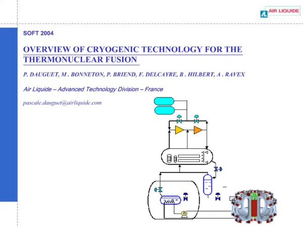
Download
1 / 20
200 likes | 385 Vues
Cryogenic Experts Meeting (19 ~ 20.09.2007). Heat transfer in SIS 300 dipole. MT/FAIR – Cryogenics Y. Xiang, M. Kauschke. Cryogenic Experts Meeting (19 ~ 20.09.2007). Outline. Heat transfer through laser cutting holes (M. Wilson, TU Dresden and GSI ) ;

E N D
Cryogenic Experts Meeting (19 ~ 20.09.2007) Heat transfer in SIS 300 dipole MT/FAIR – Cryogenics Y. Xiang, M. Kauschke
Cryogenic Experts Meeting (19 ~ 20.09.2007) Outline • Heat transfer through laser cutting holes (M. Wilson, TU Dresden and GSI ); • Temperature margin check-up for the SIS 300 dipole IHEP design by using 2D ANSYS simulation; • Optimization of the interlayer cooling channel and its connection channels based on 3D ANSYS calculation • Heat transfer analysis of 1-phase and 2-phase helium recooling process in one 300 Tm dipole; • Conclusions
Concerns on large thermal resistance due to big helium space underneath the Kapton insulation of coil cables Martin Wilson Report GSI 5 (25 Jan 2001) A calculation of 0.35 K temperature rise through a stagnant gas film, assuming the film to be 0.5mm thick. Fig 1: Gas bubble formed where Kapton wrap bulges away from cable at the edges.
Two types of Laser cutting holes on cable insulation Martin Wilson Report GSI 17 (5 Feb 2004) Fig 2: Edge view of the cable with holes cut by Jena University
Heat transfer through a hole in the electrical insulation by CFD analysis M. Hieke, H. Quack (08.12.2004) Fig. 2 – CFX model for helium flow above insulation with a hole and temperature contours (helium layer 500 mm, average velocity 0.1 m/s) Helium layer thickness: 500 mm Helium layer thickness: 20 mm heat transfer coefficient (total)
2D ANSYS analysis at GSI about the influence of cooling hole on helium flow and heat transfer (07.2004)
Observation and measurements for the cooling holes on cable insulation with microscope at GSI (13.05.2004) Type A _ cooling hole of nominal width 630 micrometers Thickness of the four layers Kapton : 102 micrometers Thickness of the four layers Kapton : 88 micrometers Thickness of the helium space underneath the four layers Kapton: 19 micrometers Thickness of the helium space underneath the four layers Kapton: 31 micrometers Depth of the helium groove in the superconductor: 100 micrometers Type B _ cooling hole of nominal width 400 micrometers The measurement shows the depth of the helium space underneath the Kapton layers is about 20 ~ 30 micon. For the cured cable it may be even smaller.
2D ANSYS analysis at GSI on the temperature margin check-up for SIS 300 6 T IHEP design (03.2006) supercritical helium (light blue), NbTi coil turns (violet), SS304 wedges (dark blue) and 0.1 mm polyimide film of insulation (not shown). Note: The cross section of the 2D model has ellipse shape because the coil is cut at 45 degree direction with respect to the magnet axis. • purposes: • to check the temperature margin of the magnet design at IHEP, Moscow • optimization the interlayer cooling channel dimensionsto ensure enough temperature margin for the magnet operation In the model no cooling holes on the insulation! no helium space underneath the insulation!
"Design of 6T superconducting dipoles for the SIS 300" IHEP report 06.05.2003. Ramping conditions of 6 T superconducting SIS 300 dipole (IHEP design) Power loss curve over one cycle Power loss curve over five cycles
Temperature profile of the inner and outer coil layers and helium flow in the interlayer cooling channel at certain time during the ramping connection channel outlet annular channel connection channel inlet Interlayer cooling channel • Highest temperature occursin the coil blocks of outer layer with many turns (poor cooling conditions) • High temperature occurs also at the turns of outer layer close to the pole (high field region); • SS304 wedges help cooling the neighboring turns Temperature profile at end of 5 ramping cycles
Temperature profile and its changes of inner-, outer-turn layers and helium flow during the ramping The calculated temperature margin of the first pole turn by ANSYSis about 0.9 K if the critical temperature for this turn is 5.69 K (IHEP 2005 report). This fits the results in the IHEP 2005 report. Time history of temperature changes at three positions in the turns and of the helium flow nearby during ramping Animation video of temperature profile during 5 ramping cycles
Temperature profile in the pole turn region and helium flow velocity when the highest temperature is reached during ramping (80 s) ~ 0.3 K at the outler layer in the pole region; ~ 0.1 K at the first turn of inner layer in the pole region; They are dominated by the temperature drop on Kapton insulation Temperature differences between the coil cable and the helium are : The average helium velocity in the interlayer is about 0.01 m/s which corresponds to the mass flow rate of 0.005 g/s
Optimization of the interlayer cooling channel and its connection channels based on 3D ANSYS calculation • purpose: • to allow as much the helium mass flow into the interlayer cooling channels as possible so as to improve the cooling performance
helix channel connection channel annular channel Optimization results discussion * Mass flow rate is kept constant at 38 g/s in the annular channel which is of 5 mm gap. The best combination is that both the helix channel and connection channels have the same height and width.
Test results of temperature profile of one Tevatron dipole (cryogenics 37, 1997) Investigation of 1-phase and 2-phase helium recooling process in SIS 300 dipole Cooling concept of SIS 300 dipole (origins from HERA [and UNK] dipole) One example to show how important is the recooling process
Heat transfer coefficients of supercritical helium, liquid helium (nucleate boiling and convection) and vapor in 2-phase recooling over 3 m dipole length Engineering Data Book III, Chapter 10, Boiling heat transfer inside plain tubes,
Temperature profile of 1-phase and 2-phase helium over 3m recooling process in one 300 Tm dipole Heat load for one dipole: 15 W 0.11 K 0.06 K Parameters of LHC dipole heat exchanger has been used for the simulation
SIS 300 dipole – guiding plate for better recooling performance
The influence of part load operation on heat transfer coefficients in 2-phase recooling process 100 % load 50 % load
Cryogenic Experts Meeting (19 ~ 20.09.2007) Conclusions • The analysis shows that the Laser cutting holes technology is an effective way to improve the cooling performance but further investigation is needed on the other aspects (strength under rapid ramping, electric insulation characteristics estimation, etc.); • Observation and measurements for the cooling holes on cable insulation shows the contribution of thermal resistance by helium space underneath the cable insulation can be neglected; • Temperature margin check-up for the SIS 300 dipole IHEP design and optimization of the interlayer cooling channel and its connection channels have been successfully done; • Heat transfer of 1-phase and 2-phase helium recooling process in one 300 Tm dipole has been simulated and ways to improve recooling performance has been discussed.