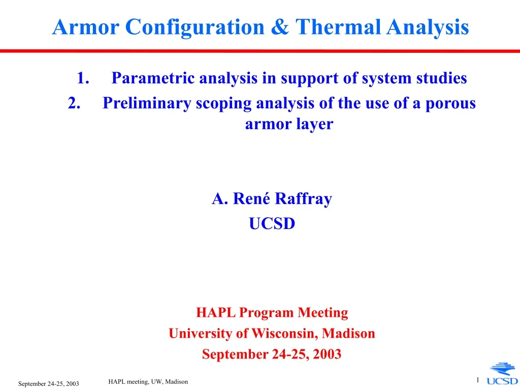
Armor Configuration & Thermal Analysis
130 likes | 147 Vues
Analysis of armor and blanket designs for chamber system studies, including temperature behavior, material properties, and heat transfer coefficients. Parameters adjusted to optimize system operation and performance.

Armor Configuration & Thermal Analysis
E N D
Presentation Transcript
Armor Configuration & Thermal Analysis • Parametric analysis in support of system studies • Preliminary scoping analysis of the use of a porous armor layer A. René Raffray UCSD HAPL Program Meeting University of Wisconsin, Madison September 24-25, 2003 HAPL meeting, UW, Madison
W FS Coolant • Use RACLETTE-IFE code in conjunction with photon and ion energy deposition models to provide series of runs to be used as input data for system studies - Update code to include a second layer in the geometry for modeling W + FS wall with a convective boundary condition at the coolant interface - Add capability to model over many cycles - Compare with other modeling results for consistency q Integrated Chamber Armor/FW/Blanket Analysis Required for Chamber System Studies • Chamber engineering constraints are set by limits on maximum temp. and cyclic temperature behavior of armor (W) and of structural material (ferritic steel), which depend on: • IFE system parameters • e.g. yield, rep rate, chamber size, protective gas density • Chamber first wall and blanket design parameters for example configuration - e.g. coolant inlet and outlet temperatures, first wall structural material thickness, armor thickness and properties (including engineered materials) and heat transfer coefficient at coolant HAPL meeting, UW, Madison
q W FS Coolant (h) Example Results Comparing W Temperature Histories for Armor Thicknesses of 0.05 mm and 0.5 mm, respectively dW=0.05mm dW=0.5mm 154 MJ yield No gas Rep Rate =10 Rchamber = 6.5 m dFS = 2.5mm Tcoolant= 500°C • Not much difference in maximum W temperature and in number of cycles to ramp up to the maximum temperature level HAPL meeting, UW, Madison
Example Results Comparing FS Temperature Histories for W Armor Thicknesses of 0.05 mm and 0.5 mm, respectively dW=0.05mm dW=0.5mm • Substantial differences in max. TFS and cyclic DTFS at FS/W interface depending on dW • Can adjust Tmax by varying Tcoolant and hcoolant • Design for separate function and operating regime: - armor function under cyclic temperature conditions - structural material, coolant and blanket operation designed for quasi steady-state 154 MJ yield No gas Rep Rate =10 Rchamber = 6.5 m dFS = 2.5mm Tcoolant= 500°C HAPL meeting, UW, Madison
Maximum TW, TFS, DTFS as a Function of Armor Thickness for Example Parameters • Maximum W temperature is virtually constant over range of armor thicknesses, ~ 3050°C • Must be integrated with chamber system modeling for consistent overall blanket and armor design parameters • For given IFE conditions and chamber parameters, set maximum possible dW (to minimize cyclic DTFS and FS Tmax and provide lifetime margin) that would accommodate: - maximum allowable TW - fabrication HAPL meeting, UW, Madison
Procedure for Parametric Armor Analysis • Utilize consistent parameters from steady state parametric study of example blanket/FW/power cycle configuration (FS/Li/Brayton Cycle) - parameters evolved on the basis of maximizing cycle efficiency while accommodating max. allowable TFS (~800°C for ODS FS) and TFS/Li (~600°C) - Tcoolant, convective heat transfer coefficient, and FS thickness set • 1-mm W thickness assumed for analysis - maintain DTFS <~20° C for example cases - also applicable for higher energy density cases as increasing the W thickness in the range of ~1 mm has only a ~10°C effect on the max. TW - could be regarded as a mid-life or end of life scenario also • For given fusion power from blanket analysis, calculate combination of yield, chamber radius and protective gas density which would maintain max. TW < assumed limit (2400 °C) - Utilize D. Haynes/J. Blanchard’s approximation to account for gas attenuation - Reduction in photon/burn ion/debris ion of 9%/1%/29% for 10mtorr Xe and R=6.5 m - Reduction of 16%/2%/48% for 20mtorr Xe and R=6.5 m - Conservative assumption: shift ion energy spectrum correspondingly - Heat in gas reradiated to surface over time 300-700 ms HAPL meeting, UW, Madison
Summary of Armor Parametric Results for a Fusion Power of 1800 MW Example target survival constraints based on allowable q’’ for case with 100mm 10% dense foam • These results are used as input in the system code in combination with results from the blanket/FW/cycle parametric analysis for the given fusion power HAPL meeting, UW, Madison
Summary of Armor Parametric Results for a Fusion Power of 3000 MW HAPL meeting, UW, Madison
Scoping Study of Thermal Performance of Armor with a Porous Layer - PPI plans to develop nano-scaled engineered W for armor applications as part of current SBIR Phase I grant • Work with PPI to help optimize material microstructure characteristics (e.g. microstructure characteristic dimension, porosity, pore sizes, heterogeneity) • Minimize resistance to migration and release of implanted He • Provide adequate heat transfer performance • Use RACLETTE-IFE with adjusted material property data and energy deposition input to help understand impact on integrated chamber armor/FW/blanket system HAPL meeting, UW, Madison
Ion Energy Deposition as a Function of Penetration Depth for a W Armor with a 10mm Porous Layer • Maximum energy deposition decreases and energy penetration depth increases with increasing porosity of the porous layer HAPL meeting, UW, Madison
Ion Energy Deposition as a Function of Penetration Depth for a W Armor with a 10mm Porous Layer • For these scoping calculations, fully dense k and r of W scaled to density of porous region • Maximum armor temp. increases appreciably with increasing porosity but not with porous region thickness past ion penetration depth (<10mm) • Important to minimize porosity of porous region but there is flexibility in setting its thickness • Porous region might reduce peak thermal stresses on armor and allow for higher max. temp. limits HAPL meeting, UW, Madison
Assessing Relative Effects of Decrease in Thermal Conductivity and Density and Change in Ion and Photon Energy Deposition Profile in Porous Region • Effect on max. TW of decrease in k in porous region dominates opposite effect due to broadening of energy deposition • Similar results for different thicknesses of porous region (10 and 100 mm) HAPL meeting, UW, Madison
Conclusions • Parametric study of armor performed to provide input for initial system studies - W thickness affects DTFS at FS/W interface but virtually not max. TW - Design armor based on transient conditions and FW and blanket based on quasi steady-state conditions - Study has yielded combination of yield, chamber radius and protective gas density which would maintain max. TW < assumed limit (2400 °C) for different fusion powers and consistent blanket/FW/cycle parameters • Scoping study of thermal performance of porous armor region has been performed - Max. TW dependent on porosity of porous region but virtually not on its thickness (past energy deposition depth) - Effect of lower thermal conductivity of porous region outweighs counterbalancing effect of energy deposition spread in porous region - Optimization of porous material based on providing least resistance to migration of implanted He ions while accommodating maximum W temperature constraint (i.e. providing acceptable heat transfer performance) HAPL meeting, UW, Madison