CS Thermal Analysis Status
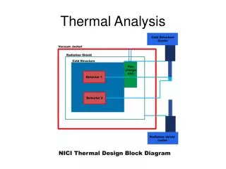
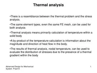
CS Thermal Analysis Status. Heating and Cooling of CS During Normal Operation - SN & DN Operation Overall Heat Balance Heating of Center Stack First Cut Thermal-Stress Analysis of CS Study of Impact of CS Tile Size on Thermal Stress. Heating and Cooling of CS During Normal Operation.

CS Thermal Analysis Status
E N D
Presentation Transcript
CS Thermal Analysis Status • Heating and Cooling of CS During Normal Operation - SN & DN Operation • Overall Heat Balance • Heating of Center Stack • First Cut Thermal-Stress Analysis of CS • Study of Impact of CS Tile Size on Thermal Stress
Heating and Cooling of CS During Normal Operation • ANSYS 2D Axisymmetric Model • CS radiatively Cooled to IBDhs, OBD, PP and VV • CS assumed perfectly insulated from OH & PF’s • CS Tiles assumed in perfect contact with Inconel Casing • IBDhs, OBD, PP and VV actively cooled • Equivalent film coefficient used – need to review and verify for new design • For CS, only modest coiling assumed at IBDhs • Single Null (SN) and Double Null (DN) modes • No Natural Divertor Mode defined in GRD (was worse case in original design) • CS Surface emissivity varied • 0.7 for Graphite (without Lithium) • 0.3 for Lithium Coated Graphite (best guess) • 14 MW, 5s pulse, 1200s rep rate • Largest Power Fraction to IBDhs • ~1/3 Power Uniformly Radiated to All exposed Surfaces
Applied Heat Fluxes Average Heat removal rate thru Cooling Systems (IBDhs, OBD, PP and VV) should total 14e6*5/1200 = 58.3 kW after fully ratcheting (see plots) Question: The GRD requirement for the CSFW is fairly modest. Are there scenarios not included here which could lead to higher heat fluxes?
End of 10th Pulse (Not yet fully ratcheted) IBDHS IBDVS CSAS CSFW
CS Inconel Casing Tavg = 342 C
Thermal Equilibration Within Tile Cooling
CS Inconel Casing Tavg = 455 C
CS Inconel Casing Tavg = 286 C
CS Inconel Casing Tavg = 370 C
Observations • Highest Tile temperatures at IBDhs where largest fraction of Power is deposited • SN much higher than DN as expected • PP Cooling picks up largest fraction of total heat with VV, OD & ID picking up comparable smaller amounts • Variation of heat load to cooling systems* not significantly different for scenarios analyzed • Highest Bulk Heating of CS Inconel Casing due to DN Operation (342C at e=.7, 455C at e =.3) *For SN all IBDhs heat load to lower cooling system
First Cut Thermal-Stress Analysis of CS • Fully Ratcheted Temperature Distribution from Previous Thermal Analysis of Single Null (highest tile temperatures) with emiss=.7 used • CS Tile thermal stress only • Assuming ATJ Structural Properties (first cut - not temperature dependent) • Initial Run as 2D axisymmetric, followed by 3D cyclically symmetric • Compares single (very) large tile to segmented tile (at Inboard Divertor Horizontal Section) • CS Casing thermal stress only • Assumes Inconel 625 Properties (first cut - not temperature dependent) • Model includes CS Casing, VV and Connecting Bellows
Temperature Distribution Following Fully Ratcheted Pulse Graphite Only
Axisymmetric No Split
Axisymmetric With Split
Cyclically symmetric No Split
Cyclically symmetric With Split
Temperature Distribution Following Fully Ratcheted Pulse (At Max CS Average Temp) Vacuum Boundary Only
Observations • Segmenting of tile Poloidally has modest affect (slightly lower Seqv) but segmenting toroidally leads to higher stresses. • Tile Stress levels (without including temperature dependency on Properties and allowables) show max stresses ~1/2 yield • Inconel Casing Stress levels are also ~1/2 yield
Study of Impact of CS Tile Size on Thermal Stress • Simplified Geometry – Segmented Cylinder • ATJ Graphite Properties assumed • 1 MW/m2 Heat Flux for 5 sec Pulse • Much Higher than GRD Spec 0.1-0.2 MW/m2 • Freely supported tile (ie unconstrained) • Stresses from Thermal Gradients • Results show stresses increase significantly with tile size
Results Results show stresses increase significantly with tile size