Understanding CPU Flags and Boolean Instructions: Impact on Operations
This overview explores the critical role of CPU flags in instruction execution, how various flags like zero, carry, sign, overflow, and parity are affected by arithmetic operations, and their implications on processing. It includes examples of flag settings based on the outcomes of arithmetic operations and the significance of boolean instructions, such as AND, OR, XOR, and NOT, that facilitate conditional processing and bit manipulation in computer architecture.

Understanding CPU Flags and Boolean Instructions: Impact on Operations
E N D
Presentation Transcript
The CPU flags • Each instruction affects the CPU flags. • The zero flag is set when the result of an operation equal zero. • The carry flag is set when an instruction generates a result that is too large (or too small) for the destination operand. • The sign flag is a copy of the high bit of the destination operand indicating that it is negative if set and positive if clear. • The overflow flag is set when an instruction generates an invalid signed result. • The parity flag is set when an instruction generates an even number of 1 bits in the low byte of the destination operand
Zero and Sign Flags: • The zero flag is set when the destination operand of an arithmetic instruction is assigned a value of zero. • example: • mov cx,1 • sub cx,1 ; cx = 0, ZF = 1 • mov ax, 0FFFFh • Inc ax ; ax = 0, ZF = 1 • Inc ax ; ax = 1, ZF = 0 • The sign flag is set when the result of an arithmetic operation is negative
Example: • mov cx,0 • sub cx,1 ; CX = -1, SF=1 • add cx,2 ; CX= 1, SF = 0 • Carry Flag: • Carry flag is significant only when the CPU performs unsigned arithmetic. • The result of an unsigned addition operation is too large (or too small) for the destination operand, the carry flag is set. • Example: • mov al, 0FFh • add al,1 ; al = 00, CF= 1
1 1 1 1 1 1 1 1 Carry: 1 1 1 1 1 1 1 1 + 0 0 0 0 0 0 0 1 0 0 0 0 0 0 0 0 • The following diagram shows what happens at the bit level • On the other hand, if we add 1 to 00FFh in ax, the sum easily fits into 16 bits and the carry flag is cleared
mov ax, 00FFh • add ax,1 ;CF = 0, ax = 0100h • If we add 1 to FFFFh in the ax register, a carry is generated out of the high bit of ax. • mov ax, 0FFFFh • add ax1 ; CF = 1, ax = 0000h • If we subtract large unsigned integer from a smaller one, the carry flag is set and the value in al is invalid. • mov al, 1 • sub al, 2 ; CF = 1
The Overflow flag: • The overflow flag is relevant only when performing signed arithmetic. • It is set when an arithmetic operation generates a signed result that can not fit in the destination operand. • Example: • mov al, +127 • add al, 1 ; OF = 1 • Similarly, • mov al, -128 • sub al, 1 ; OF = 1
Overflow has occurred if: • Two positive operands were added and their sum is negative • Two negative operands were added and their sum is positive • Overflow never occurs, when the sign of two addition operands are different. 7 6 5 CF = 1 1 1 0 0 1 1 0 1 1 0 1 1 0 1 1 0 1 1 0 1 1 0 0 0 + • Example: • When adding the binary values 10000000 and 11111110, there is no carry from bit 6 to bit 7 but there is a carry from bit 7 into the carry flag • Overflow has occurred as displayed in the following
Neg Instruction and flag • This can produce an invalid result if the destination operand can not be stored correctly • Example, if we move -128 to al and try to negate it, the value + 128 can not stored in al. • This causes the overflow flag to be set, and an invalid value to be moved to al • mov al, -128 ; al = 10000000b • neg al ; al = 10000000b, OF=1 • On the other hand 1f +127 is negated, the result is valid and the overflow flag is clear. • mov al, +127 ; al = 01111111b • neg al ; al = 1000001b, OF = 0
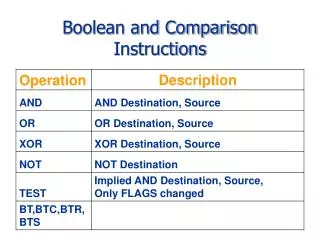
Boolean and comparison instruction • We are going to begin the study of the conditional processing by working at the binary level, using the four basic operations from the boolean algebra AND , OR, XOR, and NOT. • These operations are used in the design of the computer hardware and software. • The IA-32 instruction set contains the AND, OR, XOR, NOT, TEST, and BTop instruction which directly implement boolean operations between bytes, words and doublewords.
The AND instruction performs a boolean (bitwise) AND operation between each pair of matching bits in 2 operands and place the result in the destination operand • AND destination, source • The following operand combination are permitted • AND reg, reg • AND reg, mem • AND reg, imm • AND mem, reg • AND mem, imm
The operand can be 8, 16, or 32 bits, and they must be the same size. • The following truth table labels the input bits x and y . The third column shows the value of expression x AND y
The AND instruction is often used to clear selected bits and preserve others. • In the following example, the upper 4 bits are cleared and the lower 4 bits are unchanged • 00111011 mov a1, 00111011b • AND 00001111 and a1, 00001111b • ------------ • 00001011 • The lower 4 bits might contain useful information while we don’t care about the upper 4 bits • This technique is bit extraction because the lower 4 bits are pulled from AL • The AND instruction always clears the overflow and carry flag. It modifies the sign, zero, parity flag according to the value of the destination operand
Example: • Converting characters to upper case: • The AND instruction provides an easy way to translate a letter from a lower case to upper case. • If we compare the ASCII code for A and a, it becomes clear that only bit 5 is different • 001100001= 61h (‘a’) • 001000001= 41h (‘A’) • The rest of the alphabetic characters have the same relationship. • If we AND any character with 11011111 binary, all bits are unchanged except for the bit 5 which is clear.
The OR instruction performs a boolean (bitwise) OR operation between each pair of matching bits in 2 operands and place the result in the destination operand. • OR destination, source • The following operand combination are permitted. • OR reg, reg • OR reg, mem • OR reg, imm • OR mem, reg • OR mem, imm
The operand can be 8, 16, or 32 bits, and they must be the same size. • The following truth table labels the input bits x and y . The third column shows the value of expression x OR y
The OR instruction is often used to set selected bits and preserve others. • In the following example, 3Bh is ORed with 0Fh. The lower 4 bits of the result are set and the high 4 bits are unchanged • 00111011 • OR 00001111 • ------------ • 00111111 • The OR instruction can be used to convert a byte containing an integer between 0 and 9 into an ASCII digit. • To do this, you must set bits 4 and 5 if for example AL=05h, you can OR it with 30h to convert it to ASCII code for the digit 5 (35h)
Example: • 00000101 05h • OR 00110000 30h • ------------ • 00110101 35h, ‘5’ • The assembly language instruction to do this are as follows: • mov d1, 5 ; binary value • or d1, 30h ; convert to ASCII • Flags: The OR instruction always clears the carry and overflow flags. It modifies the sign, zero, and parity flag according to the value of the destination operand
The XOR instruction performs a boolean (bitwise) XOR operation between each pair of matching bits in 2 operands and place the result in the destination operand. • XOR destination, source • The following operand combination are permitted. • XOR reg, reg • XOR reg, mem • XOR reg, imm • XOR mem, reg • XOR mem, imm
The operand can be 8, 16, or 32 bits, and they must be the same size. • The following truth table labels the input bits x and y . The third column shows the value of expression x XOR y
X Y X + Y (X + Y) + Y 0 0 0 0 0 1 1 0 1 0 1 1 1 1 0 1 • Special Quality for XOR is that it reverses itself when applied twice to the same operand. • This reversible property of XOR makes it ideal tool for a simple form of data encryption • Flag: The XOR instruction always clears the overflow and carry flags. It modifies the sign, zero, and parity flags according to the value of the destination operand