Download
1 / 47
470 likes | 584 Vues
The Baseband Project at Rochester Institute of Technology is designed to enhance students' practical understanding of communication systems. Under the guidance of esteemed professors and experienced advisors, the project involves modulating and demodulating signals using various methods, including Amplitude Modulation, Frequency Modulation, and Pulse Code Modulation. Students will design and implement systems for both analog and digital signals, focusing on real-world applications while assessing feasibility, compliance, and system integration.

E N D
Communications Baseband Project 05500
Members • Advisors: • Dr. Joe Delorenzo • Dr. Eli Saber • Dr. Sohail Dianat • Team Members: • Leland Smith (Team Leader) • Jason Riesbeck (Chief Engineer) • Jonathan Hutton
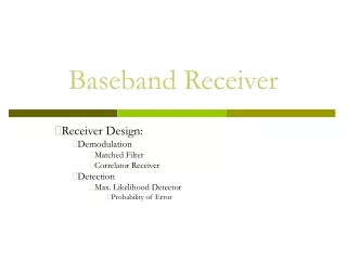
Introduction • Communications Baseband is a project created by several professors in order to stimulate student’s practical understanding of communication systems. • Sponsor: Rochester Institute of Technology Department of Electrical Engineering
Project Overview • Modulate/Demodulate using Amplitude Modulation, Frequency Modulation, and Pulse Code Modulation • Receive analog or digital transmission approximately a classrooms distance and demodulate • Output original signal to see/hear successful recovery
Preliminary Design Concept #1 Universal AM/FM/ASK/FSK System • Digital data rate • Not truly PCM • Usefulness • Two distanced RF channels • Digital and analog signals utilize common modulators • Versatile
Preliminary Design Concept #2 Analog Voice and Wireless RS232 • Not a PCM solution • Requires extra lab equipment • Duplex communication • Analog AM and FM maintained • Serial link established • Reasonable Bandwidth
Preliminary Design Concept #3 Analog Voice and Wireless USB • Difficult to implement • Requires extra lab equipment • Duplex communication • Analog AM and FM maintained • USB link established • Impressive Bandwidth • 1.5 - 450 Mbps
Preliminary Design Concept #4 Analog Voice and Streaming PCM Audio •All modulations have independent communication systems •All schemes have a common audio source ◦Impressive Bandwidth ◦Comparison of modulation schemes ◦No external equipment
System Development •Divided into 12 subsystems •Specification developed for each
Feasibility • Assessed at a subsystem level. • Depends on the resources available • To maintain feasibility, subsystems should: • Satisfy design objectives • Economical • Comply with time constraints
FCC Considerations Unlicensed Bands (FCC 15.247.b.4) Antenna gain can be as much as 6dB. All other bands 100mW or less
Audio Subsystem • Block Diagram
Anti-Aliasing Filter • Specifications: • 0-5V Input • Pass-band 20 kHz • Stop-band 22 kHz • Attenuation 20 dB • Butterworth Filter • Elliptical Filter
Low Pass Filter -17dB 22.1 kHz
AM Modulation • Concept Development • Discrete Parts • IC • Transceiver IC • Feasibility Assessment
Design Objectives and Synthesis • Clock Oscillator • 1 MHz Sine Wave • RLC Filter
AM Receiver • AM Receiver • Demodulates Signal • Amplifies the Signal by 18 dB
FM Systems • Complicated to engineer • Could take months in industry Transmitter Receiver
Radio IC’s • A simple and effective solution
FM Feasibility • Meets design requirements • •Able to be complete in allotted time • •Low cost
FSK Systems • Similar to analog FM systems • Also very complicated
FSK Feasibility • Nordic NRF2401 • Transmits data at 1Mbps • 2.4GHz ISM band
FSK Link Analysis • NRF2401 Specification ○ 0dBm output power ○ -80dBm receiver sensitivity • Link Budget Analysis ○ 60dB of attenuation at 10m (with 0dB antenna gain)
FSK Feasibility •Meets project needs •Only $4 with few external parts •Reasonable time budget
PCM and Control Subassembly • Transmit Side • Conversion of Analog to Digital • Apply Protocol to Digital Data • Manage Memory and Data Flow to FSK Chip • Receive Side • Provide Control to FSK Chip • Receive and Manage FSK Chip Data • Control and Send Data to DAC
Interface Specifications • Rail to rail (0-3.3V) analog signal input • Desire ~44 kHz Sample Rate • 1 Mbps transmit rate to FSK chip • Send samples to Digital to Analog Converter at sample rate
Microcontroller Specifications • At least 10 I/O pins • UART (clocked serial data transfer) • Support 1 Mbps
Solutions • PICmicro Microcontroller • Analog Devices DAC • 10-bit • No overhead bits • Serial
Capabilities • PIC offers 10-bit AD • PIC provides I/O ports • USART (Synchronous/Asynchronous Communications) • Many I/O Ports for control lines • Provides 1MHz USART • Data storage and management
Communications Protocol • PIC must manage data from 10-bit samples to exact 1 Mbps output • USART sends 8-bit words • Start and Stop bit • Must hold at least 2 samples in PIC memory to transfer
IN PIC OUT • Known: What goes in must come out – and at the same rate. • Therefore: The rate the PIC can sample at is governed by the FSK communications protocol. • Sampling rate must be some integer number of the outgoing packet rate
Choice Protocol • Asynchronous – 1 Sample per 2 Frames
The Plan for May • Purchase all components • Build systems to spec • Test individual systems • Integrate Systems