Power FET Structure DMOS and VMOS
230 likes | 1.17k Vues
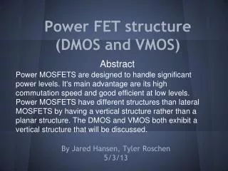
Power FET Structure DMOS and VMOS. Abstract Power MOSFETS are designed to handle significant power levels. It’s main advantages are its high commutation speed and good efficient at low levels. Power MOSFETS have different structures than lateral

Power FET Structure DMOS and VMOS
E N D
Presentation Transcript
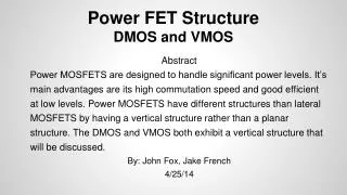
Power FET StructureDMOS and VMOS Abstract Power MOSFETS are designed to handle significant power levels. It’s main advantages are its high commutation speed and good efficient at low levels. Power MOSFETS have different structures than lateral MOSFETS by having a vertical structure rather than a planar structure. The DMOS and VMOS both exhibit a vertical structure that will be discussed. By: John Fox, Jake French 4/25/14
Outline • DMOS • What is is? • Where is it used? • DMOS Structure • VMOS • What is is? • Where is it used? • VMOS Structure
DMOS • Double diffused metal oxide semiconductor • Most Power MOSFETs are made using this technology • Used in switching applications with high voltage and high frequency behavior Typically used in: • Automobile control electronics • Inkjet printheads • Power supplies
DMOS Structure • The DMOS device incorporates a double diffusion process • The p-substrate region and the n+ source contact are diffused through a common window defined by the edge of the gate • The p-substrate region is diffused deeper than the n+ source • The surface channel length is defined as the lateral diffusion distance between the p-substrate and the n+ source
DMOS Structure • Electrons enter the source terminal and flow laterally through the inversion layer under the gate to the n-drift region • The electrons then flow vertically through the n-drift region to the drain terminal • The conventional current direction is from the drain to the source
DMOS Structure Cross-section of a double-diffused MOS (DMOS) transistor Semiconductor Physics and Devices Textbook by Donald A. Neamen
DMOS Structure • Most important characteristics are the breakdown voltage and on-resistance • The increase in resistance with temperature provides stability for the power MOSFET • DMOS is similar to a BJT, they share high-voltage and high-frequency characteristics
DMOS Structure • A lightly doped drift region between the drain contact and the channel region helps ensure a very high breakdown voltage • The n-drift region must be moderately doped so that the drain breakdown voltage is sufficiently large • The thickness of the n-drift region should be as thin as possible to minimize drain resistance
VMOS • V-groove MOSFET - a power MOSFET in which the channel region is formed along a v-shape d groove formed in the surface of the semiconductor • This MOSFET gets its name from the “V” shape groove that is formed after the p-substrate diffusion is performed over the entire surface followed by the n+ source diffusion
VMOS • VMOS power devices are used in medium voltage power supply switching applications and medium power RF amplifiers Typically used in: • Hi-fi audio power amplifiers • Broadband high-frequency amplifiers • Switching power amplifiers which convert AC power sources in DC at arbitrary voltages
VMOS Cross-section of a Vertical channel MOS (VMOS) transistor Semiconductor Physics and Devices Textbook by Donald A. Neamen
VMOS Structure • The V-groove is easily fabricated by anisotropically etching a (100) silicon surface using a concentrated KOH solution. • V shaped gate region increases the cross-sectional area of the source-drain path. • This reduces the on resistance of the device allowing it to handle high voltages
VMOS Structure • The gate consists of a metallised area over the V groove and this controls the current flow in the P region. • As the gate is fabricated in this way it means that the device retains the exceptionally high input resistance typical of the MOS family of devices.
VMOS Structure • Current flows horizontally between the source and drain, controlled by the potential on the gate. • As the current only flows through a relatively small area, resistance values can be high reducing the efficiency of the device. • One of the main drawbacks of the VMOS power device is that the structure is more complicated than a traditional FET and this makes it slightly more expensive.
Summary Power MOSFETS differ from lateral MOSFETS with the vertical structure of the DMOS and the VMOS. These are used in a variety of applications that desire high switching speeds and a variety of voltage levels. The doping and channel lengths contribute to the characteristics of each of these MOSFETS.
References Poole, Ian. "VMOS Field Effect Transistor." :: Radio-Electronics.Com. N.p., n.d. Web. 22 Apr. 2014. "V-Groove MOS (VMOS)." Electronic Circuits and DiagramElectronics Projects and Design RSS. N.p., 4 Aug. 2010. Web. 22 Apr. 2014. "Double-Diffused MOS (DMOS)." Electronic Circuits and DiagramElectronics Projects and Design RSS. N.p., 28 July 2010. Web. 22 Apr. 2014. "Double-diffused MOS (DMOS) Technology | JEDEC." Dictionary Entries. N.p., n.d. Web. 22 Apr. 2014. Van Zeghbroeck, Bart. "Chapter 7: MOS Field-Effect-Transistors." Power MOSFETs. N.p., 2011. Web. 22 Apr. 2014. Neamen, Donald A. "15.5 Power MOSFETs." Semiconductor Physics and Devices: Basic Principles. New York, NY: McGraw-Hill, 2012. N. pag. Print.
Key Points • A power MOSFET has a vertical configuration and an interdigitated gate-source surface structure • DMOS uses a double diffusion process • Most important characteristics are the breakdown voltage and the on-resistance. • V shaped gate increases the cross-sectional area of the source-drain path. • The main advantages are the high commutation speed and its good effiency at low voltages.