1.3a Current Electricity Circuit Components
1.3a Current Electricity Circuit Components. Breithaupt pages 46 to 55. October 6 th , 2010. AQA AS Specification. Charge carriers. Electric current is the flow of electric charge. This charge is carried by particles such as electrons and ions.

1.3a Current Electricity Circuit Components
E N D
Presentation Transcript
1.3a Current ElectricityCircuit Components Breithaupt pages 46 to 55 October 6th, 2010
Charge carriers • Electric current is the flow of electric charge. This charge is carried by particles such as electrons and ions. • In metals the charge carriers are negatively charged conduction electrons. They move about inside the metal, repeatedly colliding with each other and the fixed positive ions of the metal. • In other conducting substances such as acids, low pressure gases and molten salt the charge carriers consist of both positive and negative ions.
Good conductors have many free to move charge carriers. Insulators have few. • When the temperature of a semiconductor (e.g. silicon) is increased more charge carriers are produced and the semiconductor turns from an insulator into a conductor.
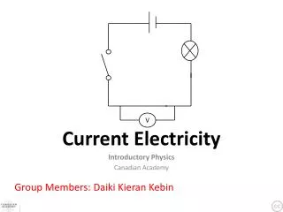
electron flow conventional current flow Conventional current flow • In electric circuits electric current is considered to flow out of the positive terminal of a power supply around a circuit and back to the negative terminal. • This convention holds even when there are no charge carriers flowing in this direction (e.g. conduction electrons in metals flow in the opposite direction). • In many conductors (e.g. cells) charge carriers, both +ve and –ve, are flowing in both directions at once. +- NTNU simulation showing charge flow and current
Current, charge and time I = ΔQ / Δt where: I = electric current in amperes ΔQ = quantity of charge moving in coulombs Δt= time in seconds for charge ΔQ to flow also: ΔQ = I x Δt and: Δt = ΔQ / I
Questions 1. Calculate the current flowing when a charge of 60C flows past a point over a period of 2 minutes I = ΔQ / Δt = 60C / 120s = 0.5 A (500mA) 2. In metals charge is carried by electrons each having -1.6 x 10⁻¹⁹ coulomb of charge. Calculate how many electrons pass a point in an electric circuit when a current of 3A flows for 10 seconds ΔQ = I x Δt = 3A x 10s = 30 C number of electrons = 30C /1.6 x 10-19 C = 1.88 x 10²⁰
Answers: Complete: 5.0 A 12 C 3 x 10⁶ s 9.6 x 10⁻³ C 4.0 A
Energy transfer in an electric circuit • The battery gives each electron a fixed amount of energy. • Chemical energy is transformed into electrical potential energy. • Work has to be done to passes electrons through devices like the bulb. • This causes the electrons to lose their electrical potential energy. • This energy is converted into thermal and light energy by the bulb.
Either side of the bulb there exists a difference in the electron’s electric potential energy. • This difference when divided by the electron’s charge is called potential difference or voltage. • The electrons return to the battery to receive further electrical potential energy.
Potential difference The potential difference across a device is equal to the work done (or energy transferred) per unit charge passing through the device. V = W / Q where: V = potential difference in volts W = the work done (or energy transferred) in joules Q = the charge moved in coulombs also: W = V x Q and: Q = W / V 1 volt is equivalent to 1 joule per coulomb
Electromotive force (emf) The electromotive force (emf) of a power supply is equal to the energy supplied per unit charge by the power supply ε = W / Q where: ε = emf in volts W= the energy supplied in joules Q = the charge supplied in coulombs also: W = ε x Q and: Q = W / ε
Questions 1. Calculate the potential difference across the bulb if 2kJ of work is required to push a charge of 250C through the bulb. V = W / Q = 2000 J / 250 C = 8.0 V 2. Calculate the energy supplied by a power supply of emf 12V when it produces a charge of 300 mC W = ε x Q = 12 V x 0.300 C = 3.6 J
Complete: Answers: 5.0 V 500 kJ 0.200 C 50 kV 3.0 x 10⁻⁵ J (30 μJ)
Electrical power V = W / Q rearranged becomes: W = VQ I = ΔQ / Δt rearranged becomes: ΔQ = I Δt or Q = I Δt Therefore when a charge Q passes through a device the work done is given by: W = V x I x Δt = I x V x Δt
But: power = work done / time Therefore electrical power, P = W / Δt = I x V x Δt / Δt Electrical power, P = I x V also: I = P / V and V = P / I with power in watts; current in A; p.d. in V
Questions on P = I V 1. Calculate the power produced by a bulb connected to a 230V power supply if a current of 50mA flows P = I x V = 0.050 A x 230V = 11.5 W 2. Calculate the current drawn from a 12V battery by a 60W device I = P / V = 60 W / 12 V = 5.0 A
Answers: Complete: 12s 720 J 60 W 15 C 9 V 135 J 60 W 2 kC 10 A 2 A 1.38 MJ 460 W
Resistance resistance = p.d. across a componentcurrent through the component R = V / I resistance in measured in ohms (Ω) potential difference in volts (V) electric current in amperes (A) also: V = I R and I = V / R
Resistance is a measure of the difficulty of making a current pass through a substance. It is caused by the repeated collisions between the charge carriers and the positive ions of the substance. Resistance simulation at PhetResistance equation demo at Phet
Questions 1. Calculate the resistance of a device if a current of 250mA flows when a potential difference of 6V is applied R = V / I = 6V / 0.250A = 24 Ω 2. Calculate the current that flows through a resistance of 4MΩ when 60V is applied across it I = V / R = 60 V / 4 000 000 Ω = 0.000 015 A = 15 μA
Answers: Complete: 6 Ω 40 V 0.5 A 20 kΩ 8 V
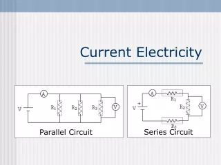
Measure the current through the resistor with the ammeter. • Measure the potential difference across the resistor with the voltmeter. • Calculate resistance using R = V / I . • Further sets of values of I and V can be obtained by changing the setting of the variable resistor. From these an average value for resistance can be obtained. • Note: The resistance of the voltmeter should be as high as possible so that the ammeter only measures the current through the resistor. • Fendt Ohm’s law simulation
Ohm’s law Ohm’s law states that the potential difference across an ohmic conductor is proportional to the current through it, provided the physical conditions do not change.
A graph of p.d. against current for a conductor obeying ohm’s law will be a straight line through the origin. • The gradient of such a graph is equal to the resistance of the conductor. • Physical conditions remaining constant include temperature and the dimensions of the conductor.
Resistivity (ρ) Experiments show that the resistance of a conductor is: 1. proportional to its length, L 2. inversely proportional to its cross-section area, A and so: R α L / A
The constant of proportionality is the resistivity, ρ of the conductor Therefore: R = ρ L A Resistivity is measured in ohm-metre, Ωm. Resistivity equation demo at Phet KT resistivity simulation
Variation in resistivity • Metals and other good conductors have very low resistivities. (e.g. copper = 1.7 x 10 – 8Ωm) • Good insulators have very high resistivities. (e.g. PVC = 1.0 x 10 + 14Ωm) • Semiconductors have intermediate resistivities. (e.g. silicon = 2.3 x 10 + 3Ωm) • Resistivity table on Wikipedia
Superconductivity • Superconductivity is a state where certain materials have zero resistivity. • This occurs at and below a critical temperature (Tc) which depends on the material. • Tc is usually below – 200oC. • Applications include: • very strong electromagnets (e.g. in MRI scanners) • power cables to prevent wastage of electrical energy (e.g. to supply the LHC)
Questions on resistivity 1. Calculate the resistance of a 0.30m length of copper wire of cross-section area 5 x 10⁻⁶ m2 [resistivity of copper = 1.7 x 10⁻⁸Ωm] R = ρ L A = (1.7 x 10⁻⁸Ωm) x (0.30m) / (5 x 10⁻⁶ m2) = 0.00102 Ω = 1.02 mΩ 2. Repeat the above question, this time with silicon [resistivity of silicon = 2300 Ωm] = (2300 Ωm) x (0.30m) / (5 x 10⁻⁶ mm2) = 1.38 x 10⁸Ω = 138 MΩ
3. Calculate the resistivity of a metal wire of cross-section diameter 0.4mm if a 25cm length of this wire has a resistance of 6Ω. A = πd2 4 = π x (4 x 10 - 4 m)2 / 4 = π x (1.6 x 10 - 7 m2) / 4 cross-section area = 1.2566 x 10 - 7 m2 ρ = RA L = (6 Ω) x (1.2566 x 10 - 7 m2 ) / (0.25 m) resistivity = 3.02 x 10 - 6 Ωm
Circuit component quizIdentify the symbols below: Answers: Circuit symbols quiz
cell - a source of chemical energy battery - a combination of cells indicator - to show the state of a circuit (on or off) also used for a filament bulb but not an LED resistor - a component designed to have resistance thermistor - resistance decreases with increasing temperature Component notes Crocodile Physics Simulations:ThermistorLDRDiode FBDiode RB
light-dependent resistor (LDR) - resistance decreases with increasing illumination diode - allows current to flow in one direction only. The allowed, ‘forward’, direction is indicated by the arrow on the symbol light-emitting diode (LED) - emits light when diode conducts Crocodile Physics Simulations:ThermistorLDRDiode FBDiode RB
Characteristic curves • These are graphs of current against potential difference that are used to show how a component behaves in an electric circuit. • Negative and positive values are plotted to show any differences in device behaviour that depend on the current direction (e.g. diode)
Variable resistor control • Potential divider control Either of the circuits shown below can be used. • This is less complicated but lower range of values obtained than with potential divider control • This is the best option but more complicated
Wire (and fixed resistors) Straight line through the origin. Obeys Ohm’s law. Note: With I-V graphs, a greater gradient means a lower resistance
Filament Lamp Resistance increases at higher currents (due to increasing temperature). Does not obey Ohm’s law.
Thermistor Resistance decreases with increasing temperature. Obeys Ohm’s law if the temperature remains constant.
Silicon diode Reverse direction (reverse-biased) Very high resistance, the current is typically below 1μA Forward direction (forward-biased) With p.d.s below about 0.6V resistance is high. With p.d.s above 0.6V the resistance falls rapidly to a few ohms and the current increases rapidly. Turn-on voltage 0.6V is known as the turn-on voltage. Different types of diode have different turn-on voltages, LEDs are typically about 1.5V. Crocodile Physics Simulations:Diode FBDiode RB
I I combination V V + 0.6 + 0.6 combination diode diode resistor resistor Diode – resistor IV combinations Sketch the IV characteristics of the diode-resistor combinations shown below. 5Ω 5Ω
1. Metallic conductors Resistance increases relatively slowly with temperature They are said to have a ‘positive temperature coefficient’ Positive ions within the conductor vibrate more with increasing temperature Charge carriers (conduction electrons) cannot pass through the conductor as easily when a p.d. is applied Resistance and temperature
2. Semiconductors Resistance decreases relatively quickly with temperature Said to have a ‘negative temperature coefficient’ The number of charge carriers increase far more rapidly with temperature than the impedance caused by the more quickly vibrating positive ions Application - the thermistor - used to sense temperature changes
Internet Links • Signal Circuit - PhET - Why do the lights turn on in a room as soon as you flip a switch? Flip the switch and electrons slowly creep along a wire. The light turns on when the signal reaches it. • Circuit Construction AC + DC - PhET - This new version of the CCK adds capacitors, inductors and AC voltage sources to your toolbox! Now you can graph the current and voltage as a function of time. • Hidden Pairs Game Circuit Pairs Quiz basic circuit symbols with this pairs game - by eChalk • Hidden Pairs Game on Circuit Symbols - by KT - Microsoft WORD • Effect of voltage on current and lamp brightness- Macleans School NZ • Effect of resistance on current flow- Macleans School NZ • Variable resistor with an ammeter & a voltmeter Resist.ckt- Crocodile Clip Presentation • Resistance measurement demo- Molecular Expressions • Ohm's Law- PhET - See how the equation form of Ohm's law relates to a simple circuit. Adjust the voltage and resistance, and see the current change according to Ohm's law. The sizes of the symbols in the equation change to match the circuit diagram. • Ohm's Law- Fendt • Thermistor Therm.ckt- Crocodile Clip Presentation • Light Dependent Resistor (LDR) LDR.ckt- Crocodile Clip Presentation • Resistance in a Wire- PhET - Learn about the physics of resistance in a wire. Change its resistivity, length, and area to see how they affect the wire's resistance. The sizes of the symbols in the equation change along with the diagram of a wire. • Resistance Wire Simulation- by KT - Designed for the GCSE Investigation but can also be used to show the affect of source resistance and to show power supply maximum power. • Conductivity- PhET - Experiment with conductivity in metals, plastics and photoconductors. See why metals conduct and plastics don't, and why some materials conduct only when you shine a flashlight on them. • Semiconductors- PhET - Dope the semiconductor to create a diode or transistor. Watch the electrons change position and energy. • Forward Biased Silicon Diode Diodef.ckt- Crocodile Clip Presentation • Reversed Biased Silicon Diode Dioder.ckt- Crocodile Clip Presentation
Core Notes from Breithaupt pages 46 to 55 • What is an electric current? • State the relationship between charge and current and give a sample calculation. • Define potential difference and give the equation for potential difference in terms of charge and work done. • What is electromotive force? • Show how the equation P = IV can be derived from the equations defining current and voltage. • What is resistance? Give the equation defining resistance and a sample resistance calculation. • What is Ohm’s law? How can Ohm’s law be verified graphically? • Give the equation for resistivity. • What is superconductivity? When does it occur? Give two applications. • Sketch and explain the shapes of the characteristic curves of (a) a metal wire; (b) a lamp; (c) a thermistor & (d) a diode • Describe and explain the resistance variation with temperature of (a) metallic conductors & (b) semiconductors
4.1 Current and chargeNotes from Breithaupt pages 46 & 47 • What is an electric current? • State the relationship between charge and current and give a sample calculation. • Explain the different ways in which a substance can conduct electricity. • Draw figure 2 on page 46 and hence explain the direction of current flow through a metal. • Try the summary questions on page 47
4.2 Potential difference and powerNotes from Breithaupt pages 48 & 49 • Define potential difference and give the equation for potential difference in terms of charge and work done. • What is electromotive force? • Show how the equation P = IV can be derived from the equations defining current and voltage. • Explain how the concept of potential difference arises from the energy transfers in an electrical circuit. • Calculate the p.d. if a charge of 50C requires 300J of work. • Calculate the current drawn by a 15W device from a 12V power supply. • Try the summary questions on page 49