Download
1 / 16
160 likes | 243 Vues
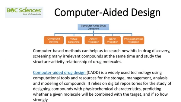
ProEngineer, a feature-based solid modeling tool, offers powerful drafting capabilities for creating parts, assemblies, and drawings. Explore its interface, modeling concepts, and design basics to work efficiently in the Eng. Industry.

E N D
MEMD261 Computer Aided DesignPro Engineer Concepts, Interface, Part Creation Basics, and Models in ProEngineer
Pro Engineer • More advance drafting software in the market. • Powerful drafting tool in Eng. Industry. • Is a solid modeler-has volume&surface area. • Allows user to input mass properties as part of model design.
Concepts1)Featured-Based • ProE is a feature-based solid modeling tool • It builds the model using individual blocks one at a time. • Examples of features are Protrusion, Cut, Hole, Chamfer, Round and etc.
2) Associative • ProE can be used to create isometric drawings, orthographic drawings, and assembly drawings. • If you change a part in an assembly, the system automatically reflects that change in any other parts and drawings of that assembly.
3) Parametric • Features are interrelated, so modifications of a single feature propagate changes in other features as well. • Relationships between features develop when one feature references another, known as a parent/child relationship.
Pro Engineer Interface Accessing ProE • Double clicking the short cut icon on the desktop. The Main Window • When you start ProE, the Main window composed of 5 areas opens on your desktop.
ProE Interface • The pull-down menus on the menu bar at the top of the window • Folder navigator: enables you to navigate folders • Web browser: to browse Web pages on Internet. • The toolbar below the pull-down menus contains shortcut commands and the toolbar on the right contains feature tools. • The display area displays the model graphic • The message area displays system messages that prompt you for required information.
Working with models • In ProE you can work with parts, drawings and assemblies. • System automatically recognizes type of the model by the extension; • .prt signifies part models • .asm signifies assembly model • .drw signifies drawing models • .sec signifies section (2D sketch)
Part Design Basics • 1) Select options(icons) that describe the general feature you want to create. • 2) Establish a sketching plane by selecting datum planes from the default datum planes system. • 3) Sketch the basic shape (2D) of the feature. • 4) Add or modify dimensions to the sketched shape. • 5) Modify and redefine the created feature.
Types of commonly used sketched features Extrude:Protrusion/Remove material Revolve Variable sweep Chamfer Round Rib Shell Hole
Some Sketcher Commands The basic sketcher tools/commands are located on the toolbar menu on the right of the screen once you start a sketcher session Pick items Create lines Create rectangles
Some Sketcher commands Create circles Create arcs Create redefining dimensions Modify dimensions Impose sketcher constraints Create text Continue with the current session Quit the current session
Functions Of The Middle Mouse Button In ProE • To SPIN-Middle mouse button:hold down and drag to rotate a model in 3-D. • To PAN-SHIFT+Middle mouse button :hold down and drag to to move the model across the screen. • To ZOOM-CTRL+Middle mouse button: hold down and drag vertically to zoom in/out. • To TURN- CTRL+Middle mouse button: hold down and drag horizontally to turn the model normal to the screen.
Models of Pro Engineer Basically there are 3 types of models: 1) Part model • .prt signifies a part model. • A part model allows you to create a 3D model consisting of features.
Models of Pro Engineer 2) Drawing model • .drw signifies a drawing model. • A drawing model allows you to create a 2D, fully dimensioned drawing of a part or assembly.
Models of Pro Engineer 3) Assembly model • .asm signifies an assembly model. • An assembly model allows you to create a 3D model in which you can assembly parts together.