Studies on active pre-alignment for the CLIC project
This study focuses on the critical aspects of active pre-alignment within the Compact Linear Collider (CLIC) project, aimed at developing a high-energy electron-positron linear collider. It addresses challenges regarding mechanical pre-alignment, beam-based alignment, and feedback mechanisms. Solutions for achieving tight pre-alignment tolerances of ±3 µm are proposed alongside the validation of these concepts on beam prototype modules. The research highlights ongoing work towards a Conceptual Design Report (CDR) and explores the strategies for precise positioning of components within the linear accelerator.

Studies on active pre-alignment for the CLIC project
E N D
Presentation Transcript
Studies on active pre-alignment for the CLIC project H. MAINAUD DURAND
SUMMARY • Introduction • Solutions for CDR • Solutions concerning re-adjustment • Solutions concerning the determination of the position • Feasibility and latest results • Validation on two beam prototype modules • Towards TDR
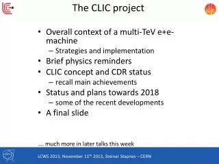
Introduction of the main challenge CLIC: Compact Linear Collider Feasibility study to develop an electron-positron linear collider (nominal center of mass energy of 3 TeV) Conceptual Design Report ready mid 2011.
Introduction of the main challenge • Relying on a two beam acceleration concept: 12 GHz RF power is generated by a high current beam (drive beam DB) running parallel to the main beam, decelerated in PETS, with generated RF transmitted to the main beam (MB) • Main linac consists of repeated sequences with a length of 2 m: modules • more than 20 000 modules in total. • The required luminosity will be reached with powerful beam colliding with extremely small dimensions (1 nm in vertical) and high stability. This can only be obtained with small emittances. As a consequence: tight pre-alignment tolerances
Introduction of the main challenge PRE-ALIGNMENT (beam off) Mechanical pre-alignment Active pre-alignment Beam based alignment Beam based feedbacks Within +/- 0.1 mm (1s) Within ± 3 mm (1s) Pre-alignment of 3 microns along a sliding window of 200 m, all along each linac After computation, for a sliding window of 200 m, the standard deviations of the transverse position of each component w.r.t. the straight fitting line must be inferior to 3 μm Determination of the position of the components in a general coordinate system thanks to alignment systems + = Active pre-alignment Re-adjustment thanks to actuators
Introduction: hypotheses for study 3 μm over 200 m (1σ) is a target for study and development. « trade off » with beam dynamics for realistic and achievable values for CDR. Budget errors Determination of the position Main linac mover requirements • Range: ± 3 mm • Step size: ~ 1 µm, resolution: ~ 0.5 µm
SUMMARY • Introduction • Solutions for CDR • Solutions concerning re-adjustment • Solutions concerning the determination of the position • Feasibility and latest results • Validation on two beam prototype modules • TowardsTDR
General strategy : re-adjustment • Several components will be pre-aligned on supports: • Along the MB: Along the DB: • RF structures on girders PETS + DB quad on girders • MB quad on interface plate DB and MB girders will be interlinked with their extremities, based on so-called cradle. This allows a movement in the transverse girder interlink plane within 3 degrees of freedom (“articulation point between girders”). (Longitudinal direction adjusted thanks to a mechanical guiding). MB quad is mounted on an interface plate, allowing an adjustment along 5 degrees of freedom (longitudinal position will be positioned manually).
Strategy of re-adjustment MB Quad // cam movers
> Strategy of re-adjustment DB and MB girders // linear actuators Concept validated in CTF2, but new design needed due to considerable increase of loads (x10).
SUMMARY • Introduction • Solutions for CDR • Solutions concerning re-adjustment • Solutions concerning the determination of the position • Feasibility and latestresults • Validation on two beam prototype modules • TowardsTDR
General strategy: determination of the position of the components Geodetic Reference Network (GRN) Backbone for all the tunnels and areas Will allow the installation of all services and of the MRN Metrologic Reference Network (MRN) • As it is not possible to implement a straight alignment reference over 20 km: use of overlapping references • For CDR: reference = wire stretched over 200 m 12
General strategy: determination of the position of the components Geodetic Reference Network (GRN) Metrologic Reference Network (MRN) Support Pre-alignment Network (SPN) 13
General strategy: determination of the position of the components Geodetic Reference Network (GRN) Metrologic Reference Network (MRN) Support Pre-alignment Network (SPN) Alignment and fiducialisation of each component on the supports (AFC) 14
Status of the different solutions Strategy towards the feasibility Stretched wire for MRN and SPN 15
SUMMARY • Introduction • Solutions for CDR • Solutions concerning re-adjustment • Solutions concerning the determination of the position • Feasibility and latest results • Validation on two beam prototype modules • TowardsTDR
Required solutions: feasibility of the concept ISSUES STEPS Stable alignment reference, known at the micron level Determination of the metrological network w.r.t the straight alignment reference Submicrometric sensors providing « absolute » measurements Determination of the position of each sensor w.r.t metrological network Fiducialisation: determination of the zero of each component w.r.t the sensor (external alignment reference) Activepre-alignment Measure 2m long objects within a few microns Re-adjustment: displacement of the component supporting structure according to the sensor readings Submicrometric displacements along 3/5 DOF Other issues: Compatibility with the general strategy of installation and operation Compatibility with other accelerator equipment or services 17
Re-adjustment: feasibility and latest results Validation of a SLS type cam mover (1 DOF mock-up) MB Quad // cam movers Tested with 3 configurations of bearing and outer rink Sub-micron repeatability achieved on full stroke with every configuration Validation of on a 5 DOF mock-up Mock-ups ready end of 2010
Re-adjustment: feasibility and latest results DB and MB girders // linear actuators Design of a new “articulation point” concept Validation on a pre-alignment mock-up Mock-ups ready end of 2010
Determination of the position: feasibility and latest results Stretched wire • Main issue: long term stability of a wire • (effects of temperature, humidity, creeping effects, air currents) • Modelization of the wire using Hydrostatic Levelling Systems (HLS) • but only in the vertical direction • but HLS system follows the geoid which needs then to be known • studies undertaken concerning the determination of the geoid • Is a stretched wire really straight (radial direction)? • First idea: comparison with a laser beam under vacuum (NIKHEFF) • on short distances (50 m) this autumn at CERN • Subject of two PhD theses: • « Determination of a precise gravity field for the CLIC feasibility studies » (S. Guillaume) • « Analysis and modeling of the effect of tides on Hydrostatic Leveling System » (J. Boerez)
Stretched wire and MRN Minimum configuration TT1 facility • Objectives: • To determine the precision and accuracy of a MRN consisting of overlapping stretched wires • To study the behavior of wires of different lengths • To study the modelization of a stretched wire
Stretched wire and MRN Results in TT1 • Precision on a 140 m wire: better than 2 microns over 33 days • Accuracy: 11 microns in vertical, 17 microns in radial. Can be improved! • Vertical residuals of the 2 longest wires: • σ (wire 1) = 1.6 µm • σ (wire 2) = 0.5 µm • Accuracy of the TT1 network adjusted by the least squares method in vertical: • σ = 11 µm r.m.s (27 µm max. value) • Subject of a PhD thesis: «Proposal of an alignment method for the CLIC linear accelerator: from the geodetic networks to the active pre-alignment» (T. Touzé)
Sub-micrometric sensors • Issue: WPS sensor fulfilling the requirements • « absolute measurements » (known zero w.r.t mechanical interface) • no drift • sub micrometric measurements Upgrade of an existing WPS Development of a new WPS Capacitive basedWPS (cWPS) Optical based WPS (oWPS) Resolution: 0.2 µm Range: 10 x 10 mm Repeatibility: 1 µm Bandwidth: 10 Hz
Status of fiducialisation Issue: measure 2 m long objects within a few microns • First solution: CMM measurements (dimensional control, pre-alignment of components on their supports, fiducialisation), but STATIC • Alternative solution: use of Laser Tracker in lab and tunnels (control after transport, during tests,…) • Laser Tracker from LEICAAT401: • Maximum offset in the determination of a point in space: ± 15 µm + 6ppm (3σ) • Maximum offset in the determination of distance between 2 points: 10 µm • Centering of target: ± 2.5 µm (3σ) 25 25
Inter-comparison between sensors: Web site: https://clic-pral.web.cern.ch/clic-pral/ • Status of the inter-comparison: • WPS [SLAC, CERN] : inter-comparison at SLAC. Facility ready in July 2010. • HLS [Fermilab, SLAC, DESY, USTC]: long term stability tests at Fermilab, other tests at CERN.
SUMMARY • Introduction • Solutions for CDR • Solutions concerning re-adjustment • Solutions concerning the determination of the position • Feasibility and latest results • Validation on two beam prototype modules • TowardsTDR
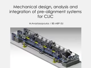
Proposed solution for two beam prototype modules (N. Chritin) • Validation of the repositioning concept (possibility of sub-micrometric displacements) • Before the installation of all other systems (waveguides, vacuum,…) • After installation of all other systems (waveguides, vacuum,…) • Measurement of the eigenfrequencies of the girders • Validation of the fiducialisation strategy • Validation of the stability of the components on the girders • Impact of the transport on a micrometric pre-alignment • Impact of variation of temperature, thermal cycles • Feedback for the CLEX test module, and all associated technical specifications • Feedback for the general strategy of installation • Feedback for the schedule • Inter-comparison between solutions of SPN networks. 29
SUMMARY • Introduction • Solutions for CDR • Solutions concerning re-adjustment • Solutions concerning the determination of the position • Feasibility and latest results • Validation on two beam prototype modules • Towards TDR
Alternative studies for TDR • Determination of the position of the components: • In collaboration with NIKHEF : development of alternative solutions (laser beam) • Design of a short range / long range solution adapted for CLIC requirements • Integration of the short range solution on the two beam prototype modules • Inter-comparison of the long range solution in TT1 / TZ32 tunnels Re-adjustment: Validation of the concept of articulation point with cam movers Other studies (in order to reduce the number of sensors): Study of a mono-girder (DB & MB components) Study of longer girders Development of low cost WPS sensors with FOGALE Nanotech (technical specification under definition) • Development of a Laser Alignment Multipoint Based: LAMBDA project
LAMBDA Project • LAMBDA for Laser Alignment Multipoint Based – Design Approach • Description: • Reference of alignment : laser beam under vacuum • N-point alignment system: sensors distributed along the beam • Speckles are measured on a surface on each point (sensor) using a CCD • Measurement surface = mechanical or optical shutter, which will not alter the beam and keep the straightness of the reference of alignment. • Each sensor consists of a measurement surface, a convergent lens and a CCD camera, allowing an indirect observation of the speckles on the surface by the CCD • reducing the angular sensitivity of the system. • According to the first simulations, to detect micometric displacement, angular orientation should be better than 0.2 mrad, and repeatability of shutter 12 µm • Status: looking for a PhD student. (F. Lackner)
CONCLUSION Proposed solution for CDR Determination of the position of the components: stretched wire + WPS sensors for MRN and SPN Re-adjustment: MB quad: cam mover Girders: high precision linear actuators Feasibility will be endorsed on the CLIC prototype modules