
SlideServe
Menu
Préférences
© SlideServe · v2026

Active Alignment System for the LSST

kamala avatar
19 diapositives · 472 Views · Sep 10, 2014

Active Alignment System for the LSST. Introduction. Large Synoptic Survey Telescope (LSST) Optical Design/Layout Operational Requirements Active Alignment System System Definition Alignment Requirements Design Methodologies Spatial Analyzer (SA) Effort SA Model Description
Active Alignment System for the LSST - slide 1
01 / 19Active Alignment System for the LSST
1 / 17

Télécharger la présentation

Active Alignment System for the LSST
Une image / un lien ci-dessous est fourni (tel quel) pour télécharger la présentation

Politique de téléchargement : le contenu du site vous est fourni TEL QUEL pour votre information et votre usage personnel ; il ne peut être vendu, concédé sous licence ni partagé sur d’autres sites sans l’accord de son auteur.Le contenu vous est fourni TEL QUEL, pour votre information et votre usage personnel uniquement. Téléchargez la présentation en cliquant sur ce lien. Lors du téléchargement, si vous ne parvenez pas à télécharger une présentation, l’éditeur a peut-être supprimé le fichier de son serveur.Pendant le téléchargement, si vous ne parvenez pas à obtenir une présentation, le fichier a peut-être été supprimé par l’éditeur.

F I N

Plus de contenu associé

Transcription de la présentation
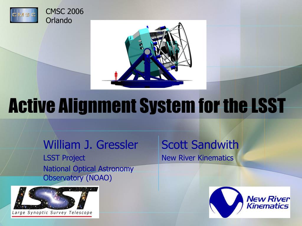
  1. Active Alignment System for the LSST

  2. Introduction • Large Synoptic Survey Telescope (LSST) • Optical Design/Layout • Operational Requirements • Active Alignment System • System Definition • Alignment Requirements • Design Methodologies • Spatial Analyzer (SA) Effort • SA Model Description • Technologies Reviewed • Performance Analysis

  3. M2 Camera • M1/M3 LSST Optical System • Modified Paul-Baker Design • f/1.23 • 3.5 Degree FOV • 3-Mirror Telescope • Unique 8.4m M1/M3 • 3.4m M2 • Camera • 3 Refractive Lenses, 6 Filter Bands • 63cm Detector • 3 Billion Pixels/Image! • 15 Tbytes/night, 5 Pbytes/yr

  4. 0.2 degrees 10 m 8.3 m LSST Product of areas measures survey capability Etendue = 319 m2deg2 LSST Comparison Field of view (full moon is 0.5 degrees) Primary mirror diameter 3.5 degrees Keck Telescope

  5. Optics Subsystem Layout • 3 Major Optical Subsystems • M1/M3 Provides Reference Optical Axis • M1/M3 & M2 Active Figure Control • M2 & Camera Hexapods for Rigid Body • Telescope Survey Operational Cadence • Open Shutter  15sec Exposure • Close Shutter  2sec Readout • Repeat Sequence for 2nd Exposure • 5sec Slew to Next Field • Maintain Alignment During Operation

  6. Telescope Control System (TCS) • TCS Delivers Best Possible Image to Camera • Multiple Inputs • Operator • Enclosure • Mount • Sky Camera • Weather Station • Wavefront Sensing System • Active Alignment System

  7. Camera Wavefront Sensing • Wavefront Sensors w/in Camera Focal Plane • Baseline Curvature Sensors • Provides Mirror Figure Control & Rigid Body Positioning • No Information While Shutter Closed Wavefront Sensors (4 locations) Guider Sensors (8 locations) Potential Aux. Sensors (16 locations) 3.5 degree Field of View (63 cm diameter) Sensor Package (9 per Raft) Raft (21 in FPA)

  8. Active Alignment System Description • Complementary to Focal Plane Wavefront Sensing • Supports Telescope Alignment • Initial Site Installation/Mount Model Development • Re-Assembly after Repair, Recoating, etc. • Perform Start of Night Operational Setup • Maintain Alignment of 3 Major Subsystems • M1/M3 Reference • M2 Position (5 DOF) Camera Position (5 DOF) Hexapods

  9. Active Alignment System Requirements • Define Subsystem Fiducials • Fiducials Define Optical Axis • Locate on Telescope Mount, M1/M3, M2, & Camera • Incorporate into Final Factory Acceptance Testing • Measure Fiducials to Maintain Subsystem Alignment LSST Alignment Requirements

  10. System Design Constraints • Packaging/Line of Sight Issues • No Interference w/ Light Rays • See Fiducials for Measurements • Operational Needs • Ease of Service / Calibration • No Heat/Vibration • Support Full Telescope Pointing (Zenith to Horizon) • Operational Temperature Range -10C to +25C • Minimal Warm-up Time Allowed • High Altitude/Low Pressure • Sufficient Measurement Speed – 30 Second Cadence • Incorporate into TCS for Closed-Loop Feedback • Provide Required Accuracies

  11. Light Sources • Measurement Light Sources Must Minimize Camera Science CCD Impact • l>1mm Preferred (also ~400nm & ~950nm) • Pointing system technology (wavelength) • Ranging system technology (wavelength) Camera Focal Plane Transmission (Ideal Filters, Optics, Atmos, QE)

  12. System Development Approach • Study Effort w/ NRK to Define Active Alignment System using SA Modeling • Baseline Definition & Performance Prediction • Establish Handoff to Wavefront Sensing System • Uncertainty Analysis for Metrology Controlled Optical Alignment System • Review Various Technologies • Laser Tracker • Laser Radar • Videogrammetry

  13. Measurement Network Simulation

  14. Uncertainty Field Analysis • Metrology Network Optimized (Range Weighted Optimization)  Composite Points • Uncertainty Fields Established for Each Composite Measured Target • Uncertainty Estimate for Telescope Mirror/Camera Computed with Sets of Target Uncertainty Clouds in Over-Determined Circle, Planar, and Cylindrical Shape (Monte-Carlo) • Centering • Normal Direction Pointing • Focus Position

  15. Metrology System Uncertainty Analysis

  16. Tilt Uncertainty Analysis vs. Num of Pts

  17. Uncertainty Analysis Conclusions • LSST SA Model Results • 3 Metrology Systems Analyzed: (Laser Tracker, Laser Radar, & Videogrammetry) • Each System Capable of Meeting Requirements for Relative Subsystem Position/Orientation • No Perfect Solution (Source l Issues, Total Measurement Time, etc.)

  18. Planned Future Activity • Continued System Development • Define Fiducial Geometries for Major Telescope Subsystems • Engage Metrology Device Vendors • Review Requirements • Explain Current Deficiencies & Needs • Perform Measurements at Nearby AZ Telescope Sites (Similar Operating Conditions) w/ Existing Commercial Hardware

  19. What the sky will look like with LSST • Survey image shown is ~0.5 degree field from Deep Lens Survey Project • Shows roughly ten times as many galaxies per unit area (vs. Sloan Digital Sky Survey) • The LSST images will cover 50,000 times this area in 6 different optical bands (20,000 sq. degrees!) • LSST will show changes in the sky by repeatedly covering this area - multiple times per month • 250,000 Type 1a supernovae detected each year QUESTIONS/COMMENTS