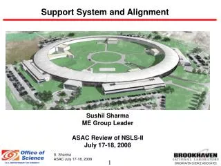
the RASNIK Alignment System
the RASNIK Alignment System. Particle Physics CERN, Geneva, Swiss. pp collisions. 2) heavy collisions: A proton is a bag filled with quarks en gluonen. The ATLAS Experiment CERN, Geneva, Switzerland. ‘Tracking’ of charged particles Measurement of position of tracks
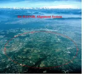

the RASNIK Alignment System
E N D
Presentation Transcript
Particle Physics CERN, Geneva, Swiss
pp collisions 2) heavy collisions: A proton is a bag filled with quarks en gluonen
The ATLAS Experiment CERN, Geneva, Switzerland ‘Tracking’ of charged particles Measurement of position of tracks Track curvature: measure for momentum & energy
Momentum Measurement of charged particles in the L3 experiment: Chamber Position Monitoring Detector Detector Detector Muon Particle Track • Lorentz Force: • Track Curvature measurement
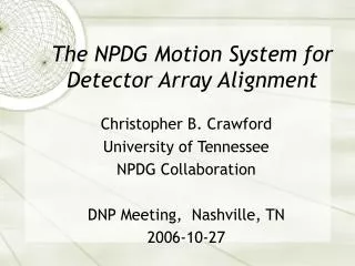
Principle of CCD-RASNIK Light Source Lens CCD Coded Mask
Title: The RASNIK opto-electronic alignment system: a high-precision, large range, fast and zero-drift monitor for displacements or deformations. In RASNIK, the image of a (back-illuminated) coded mask is projected, by means of a lens, onto a (pixel) image sensor. A displacement of the mask, or lens, or sensor, relative to the other two components, results in a displacement of the mask’ image on the sensor. This can be registered accurately by means of a processor connected to the (USB) sensor. Displacements in the two transversal directions cause an image shift, and a displacement in the direction of the optical axis results in a change of the image scale. In addition, the relative rotation around the optical axis of mask and sensor can be recorded, making RASNIK a 4D measurement device. With image frame rates up to 100 Hz, vibrations can be measured as well. With RASNIK, the bending of a (roof) bar can be monitored accurately. When the lens and sensor are coupled on one (CAM) base plate, the displacement of the mask with respect to this base plate is measured; this ‘proximity’ RASNIK is applied as displacement monitor for adjacent tunnel sections. The deformation of a complete tunnel could be measured by mounting a series of identical plates, each carrying a mask, lens and sensor, forming a chain of coupled RASNIK systems.
dXLED = -2 dXLEN = dXSEN • Rasnik 3-point alignment system • Alternatives: • Taylor Hobson telescope • Stretched wire system: electronic version after 1985
Measurement & Precision • Translation (X, Y): 50 nm per image • Scale: 1.0000 +/- 0.00001 • Rotation around Z-axis: 0.1 mrad • Number of images: depending on pixel sensor: • - webcam: 30 – 60 images per second: measurement of vibrations! • - special graphic image sensor: 10.000 images/s Practical limitation: Temperature gradient in air Image info ~ 1Mb is converted into only 4 parameters dT
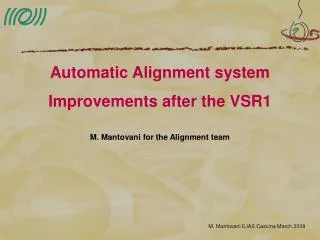
ATLAS Muon Chambers Light Sources Lenses Image Sensors • RASNIK ‘In-Plane’ systems • Measures: • Chamber sag • Chamber torque • Temperature gradients
RASNIK systems in the ATLAS Muon Spectrometer Axial Proximity ‘Praxial’ Projective
4 D, no-contact Dial Gauge mask lens Image sensor laptop Applications
Weena Rasniks Measurement of relative displacement of adjacent sections
RasChain • Intergral measurement, in 3D, of deformation of large (long) object: • tunnel • bridge • RasChain plate includes light source, lens and image sensor • mount RasChain plate at ~ 10 m pitch, over 1 km • readout chain at both ends • Deformation is measured with mm precision!
Segment2 m Laser Diffraction plate (hole) RasChain Image sensor
IDaddress µC Laser Link Diffraction plate (hole) Image sensor Microcontroller data power Bus and Power
Level 0 link Cameras on a bus
~128m Level 0 ChainControl Level 1 Communication layer Next chain~256m Chain
RasChain measuring the integral deformation of a long object, i.e. a tunnel
Fig. 1 The leap-frog Rasnik system. All plates are identical and each include an illuminated coded mask, a lens and an image sensor.
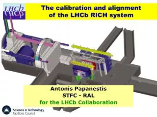
Position resolution with Gaussian noise on Rasnik data The noise per Rasnik system is rather arbitrary. With direct shadow images, 50 nm has been achieved (image position on sensor: XR and YR). With RasDif, 20 nm has been reached (over 140 m!). If images of a static system are combined, even lower values are reached. The lower limit is hard to measure due to the presence of systematic image shifts due to non-homogeneity of the ambient medium, causing both a random and a systematical error. Assuming a random Gaussian error in XR of 50 nm in all of the 100 Rasnik systems, the resulting errors in the monitored plate positions is shown in fig.2. As expected, the uncertainty is the largest in the middle of the RasChain. The value, however, is in the order of 10 µm and small enough to be relevant for the presence of long-distance alignment systems such as (long) RasClic or the stretched wire system.
Fig. 2. The random error as a function of plate number, due to a Gaussian error of 50 nm on the Rasnik data (common for all 100 systems).
RasDif: replace lens by diffraction plate: just a round hole! RasCam Laser zone lens hole dia. 50 mm 100 m (vacuum tube!)
RasDif long baseline: lens becomes unpractical Replace lens by ‘diffraction plate’: just a hole! RasCam Laser expanded beam just monochromatic light source diffraction plate hole dia. 50 mm
Rasnik as seismic sensor Image position on sensor. Response of earthquake in Mid-Atlantic, 5 Richter Scale, on March 1, 2007
RasNap Air-refraction corrected telescope Practical limitation: Temperature gradient in air
Rasnik: a new displacement monitor • based on a wide and 27 years long experience • very precise: • high data rate: dynamical measurement • no drift in measurement: monitoring of slow motions • simple, digital, robust & low-cost • a new means of product parameter verification • But: • needs 220 V and Ethernet (compare old t, P-sensor: plot) • custom/case-specific application (use ‘standard’ components) • - interpretation of data: skilled, educated personel