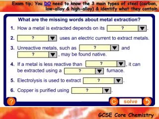
STEELS
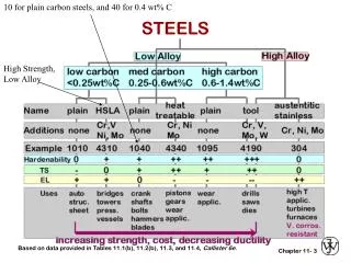
STEELS. 10 for plain carbon steels, and 40 for 0.4 wt% C. High Strength, Low Alloy. Based on data provided in Tables 11.1(b), 11.2(b), 11.3, and 11.4, Callister 6e. 3. NONFERROUS ALLOYS. Based on discussion and data provided in Section 11.3, Callister 6e. 4. REFINEMENT OF STEEL FROM ORE.

STEELS
E N D
Presentation Transcript
STEELS 10 for plain carbon steels, and 40 for 0.4 wt% C High Strength, Low Alloy Based on data provided in Tables 11.1(b), 11.2(b), 11.3, and 11.4, Callister 6e. 3
NONFERROUS ALLOYS Based on discussion and data provided in Section 11.3, Callister 6e. 4
REFINEMENT OF STEEL FROM ORE (coal residue) 5
METAL FABRICATION METHODS-I FORMING • Forging (wrenches, crankshafts) • Rolling (I-beams, rails) often at elev. T Adapted from Fig. 11.7, Callister 6e. • Drawing (rods, wire, tubing) • Extrusion (rods, tubing) 6
FORMING TEMPERATURE • Hot working --recrystallization --less energy to deform --oxidation: poor finish --lower strength • Cold working -- no recrystallization -- more energy to deform -- no oxidation: good finish -- higher strength • Cold worked microstructures --generally are very anisotropic! --Forged --Swaged --Fracture resistant! (a) (b) (c) Reprinted w/ permission from R.W. Hertzberg, "Deformation and Fracture Mechanics of Engineering Materials", (4th ed.), John Wiley and Sons, Inc., 1996. (a) Fig. 10.5, p. 410 (micrograph courtesy of G. Vander Voort, Car Tech Corp.); (b) Fig. 10.6(b), p. 411 (Orig. source: J.F. Peck and D.A. Thomas, Trans. Metall. Soc. AIME, 1961, p. 1240); (c) Fig. 10.10, p. 415 (Orig. source: A.J. McEvily, Jr. and R.H. Bush, Trans. ASM55, 1962, p. 654.) 7
METAL FABRICATION METHODS-II CASTING • Sand Casting (large parts, e.g., auto engine blocks) • Die Casting (high volume, low T alloys) • Continuous Casting (simple slab shapes) • Investment Casting (low volume, complex shapes e.g., jewelry, turbine blades) plaster die formed around wax prototype 8
METAL FABRICATION METHODS-III JOINING • Powder Processing (materials w/low ductility) • Welding (when one large part is impractical) Adapted from Fig. 11.8, Callister 6e. (Fig. 11.8 from Iron Castings Handbook, C.F. Walton and T.J. Opar (Ed.), 1981.) • Heat affected zone: (region in which the microstructure has been changed). 9
THERMAL PROCESSING OF METALS Annealing: Heat to Tanneal, then cool slowly. Based on discussion in Section 11.7, Callister 6e. 10
THERMAL PROCESSING OF METALS Based on discussion in Section 11.7, Callister 6e. 10
HARDENABILITY--STEELS • Ability to form martensite • Jominy end quench test to measure hardenability. Adapted from Fig. 11.10, Callister 6e. (Fig. 11.10 adapted from A.G. Guy, Essentials of Materials Science, McGraw-Hill Book Company, New York, 1978.) • Hardness versus distance from the quenched end. Adapted from Fig. 11.11, Callister 6e. 11
WHY HARDNESS CHANGES W/POSITION • The cooling rate varies with position. Adapted from Fig. 11.12, Callister 6e. (Fig. 11.12 adapted from H. Boyer (Ed.) Atlas of Isothermal Transformation and Cooling Transformation Diagrams, American Society for Metals, 1977, p. 376.) 12
HARDENABILITY VS ALLOY CONTENT • Jominy end quench results, C = 0.4wt%C Adapted from Fig. 11.13, Callister 6e. (Fig. 11.13 adapted from figure furnished courtesy Republic Steel Corporation.) • "Alloy Steels" (4140, 4340, 5140, 8640) --contain Ni, Cr, Mo (0.2 to 2wt%) --these elements shift the "nose". --martensite is easier to form. 13
QUENCHING MEDIUM & GEOMETRY • Effect of quenching medium: Medium air oil water Hardness small moderate large Severity of Quench small moderate large • Effect of geometry: When surface-to-volume ratio increases: --cooling rate increases --hardness increases Position center surface Cooling rate small large Hardness small large 14
PREDICTING HARDNESS PROFILES • Ex: Round bar, 1040 steel, water quenched, 2" diam. Adapted from Fig. 11.18, Callister 6e. 15