Download
1 / 9
90 likes | 358 Vues
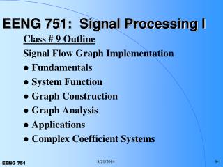
Lab. 7 Signal Transmission between DSP and ADC/DAC DAC/ADC/FGPA module: With DAC/ADC, digital systems can be communicated with the analog world. Digital. Digital. Analog. DSP. PC. DAC ADC. FPGA. Ethernet. EMIF. IQ board: provide I/Q connectors for the DAC/ADC.

E N D
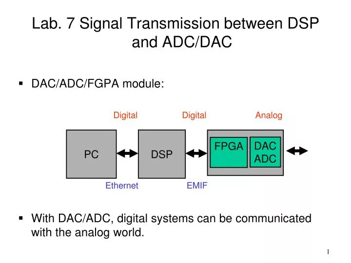
Lab. 7 Signal Transmission between DSP and ADC/DAC • DAC/ADC/FGPA module: • With DAC/ADC, digital systems can be communicated with the analog world. Digital Digital Analog DSP PC DAC ADC FPGA Ethernet EMIF
IQ board: provide I/Q connectors for the DAC/ADC. • There are 4 channels (2 inputs/2 outputs) and each channel has IQ components (differential). Thus, we have total 16 SMA connectors. • EMIF interface routines in both FPGA and DSP have been built. All you have to do is call the related C functions when you want to conduct I/O. FPGA DAC ADC * Can be replaced by RF board
How to call the EMIF routines? • Step 1: Copy the given files to your project: (1) hello.c, (2) edma.c, (3) interrupt.c, (4) intvecs.asm, (5) psc.c • Step 2: Declare five functions in your main C file. • Step 3: Call the function F_StartEMIFA (.) first for initialization (only do that for one time). • Step 4: Call the function F_SetTxBlkGp(.) to start transmit or F_SetRxBlkGp (.) receive data from FPGA through EMIF (Call this function when you want to do TX or RX task).
Note that the unit of TX and RX buffer are 1K, and the variable format is short (2 Bytes). However, we do not use all bits to transmit data. In TX direction, we only use the 10 bits in the end of a short word (16 Bits), and in RX direction, we only use the 12 bits in the end of a short word (16 Bits). • Also, the DAC is unsigned. Thus, the signal has to be quantized and mapped.
Q+ Q+ Q+ Q+ I+ I+ I+ I+ I- I- I- I- Q- Q- Q- Q- • The input/output of DAC/ADC are differential, meaning that you have two pairs of wires. • The IQ board: • The demo program outputs both I and Q signal. For Tx experiment, you can either use I or Q for the scope. RX experiment RX/ADC TX/DAC Or TX experiment
Tx experiments: • Use DSP to generate periodic signals and use a scope after DAC to observe the output • Practice 1: • Generate a sinusoidal signal in DSP. • Generate a triangular wave in DSP. • Observe the signal on scope (in one channel). • Calculate the frequencies of the observed signals, and find the relationship between the analog and digital frequencies. • Adjust the peak values of the signals and see the output results. DSP PC DAC ADC FPGA Ethernet EMIF
Rx experiments: • Use a function generator (FG) to generate periodic signals and input the signals to the ADC. • Practice 2: • Generate sinusoidal and triangular signals with the FG. • Observe the signal in DSP. • Calculate the frequencies of the observed signals, and find the relationship between the analog and digital frequencies. • Adjust the peak values of the signals and see the output results. • Adjust the frequency of the input signal. DSP DAF FG
Q+ Q+ Q+ Q+ I+ I+ I+ I+ …….. I- I- I- I- Q- Q- Q- Q- • Since the function generator is single-ended, we tie one of a differential pair to the ground. • Grounding: Ground Function generator
Loop-back experiments: • Use DSP to generate periodic signals and loop back the signal from DAC to ADC. • Practice 3: • DSP generates a triangular wave and let the signal loop back. • DSP saves the received signal into a file. • Read the file and plot the signal to check if it is right. DSP PC DAC ADC FPGA Ethernet EMIF