Download
1 / 83
830 likes | 1.13k Vues
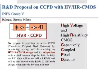
D ESIGN O F H IGH P ERFORMANCE C ONCRETE ( HPC ) M IXTURE I N A GRESSIGE E NVIRONMENT. United Arab Emirates University College of Engineering Civil and Environmental Engineering Department Graduation Project II. Prepared by: Saeed Khamis Al Haddadi 200203853

E N D
DESIGN OF HIGH PERFORMANCE CONCRETE (HPC) MIXTURE IN AGRESSIGE ENVIRONMENT United Arab Emirates University College of EngineeringCivil and Environmental Engineering DepartmentGraduation Project II Prepared by: SaeedKhamis Al Haddadi 200203853 Nayel Rashid Al Shamsi 200216968 MansourMohd Al Shebli 200204979 SaeedNahyan Al Ameri 200204458 MuathMohd Al Mazrooei 200205340 Adviser’s name: Dr. Amr S. El Dieb 2st Semester 2007/2008
Outlines… Introduction Objective Mix Design Methods Experiment and Testing Gant Chart
Introduction… • HPC is defined as concrete which meets special performance and uniformity requirements that cannot always be achieved by using only the conventional materials • Concrete is composed principally of aggregates, Portland cements, water, and may contain other cementations materials and/or chemical admixtures.
Introduction… • The selection of concrete proportions involves a balance between economy and requirements for place ability, strength, durability, and density (i.e. its performance). • HPC is characterized by its high performance in any of its properties or characteristics • Usually the term HPC is used to define high durable concrete (i.e. concrete characterized by high durability)
Impact Concrete Environment Impact Concrete Environment Resistance Deterioration Durable Concrete (HPC) • Introduction… • The required durability characteristics are governed by the application of concrete and by conditions expected to be encountered at the time of placement. These characteristics should be listed in the job specifications.
Objective… • The effect of different SCM with various dosages on HPC mixes will be evaluated for various aggressive environments. • Different concrete mix design methods will be implemented and compared to design HPC mixes. • Control concrete mix will be designed having a compressive strength of 40 to 50 MPa, slump between 100 – 120 mm and the cement content is 350 kg/m3.
Mix Design Methods… • There are two well known mix design methods implemented by various codes : • BS 8328 mix design method. • ACI 211.1-91 mix design method.
Mix Design Criteria • To perform a concrete mix design several criteria (i.e inputs) are needed together with the properties of the used materials • The criteria needed includes: • Required strength • Required slump • Minimum cement content • Properties of available or used materials; investigated in GPI
BS Method Approximate compressive strength (N/mm2) of concrete mixes made with a free water/cement ratio 0.5
BS Method.. Relationship between compressive strength and free water-/cement ratio From this graph w/c ratio is determined for the required strength 47 0.47
BS Method Approximate free water content (Kg/m3) required to give various levels of workability. Slump is adjusted by admixture dosage
BS Method Estimated wet density of fully compacted concrete to calculate the aggregate quantity 2420 170
BS Method Determines the mixing ratio of fine and coarse aggregates depending on the grading zone of the fine aggregate (1,2,3 &4)
BS Method… 35%
ACI Method… Relationship between water-cement or water- cementations materials ratio and compressive strength of concrete
ACI Method… Approximate mixing water and air content requirements for different slumps and nominal maximum sizes of aggregates
ACI Method Volume of coarse aggregate per unit of volume of concrete
Discussion • After we used two methods we found ACI method is not appropriate to design our control mix because the maximum strength we can design using this method is 34 MPa and it is using cylinder not cube so BS method is used. • Also there isn’t any mix design method which considers the incorporation of supplementary materials such as Slag and Silica fume. • Typical concrete mix used in the country is designed using material investigated in GPI.
Criteria for mix design • Parameters: • Silica fume • Slag • Combination of silica fume and slag • Many ready mix company in my country used silica fume in range of 8% and slag in range of 40% to 60% of cement content. • We will use 5% , 8%, and 15% of silica fume to make comparison between it. • Also we will used 25%,40% and 60% of slag to compare between it. • In addition, we will study the ternary blends ( silica fume and slag ).
Criteria for mix design Strength 40-50 MPa Slump 100- 120 mm“ controlled by admixture C.C. at least 350 kg/m3 Mix Proportions/ m3 Batch Quantities
Introduction SCM • SCM usually works in two ways: • As microfilling materials i.e. physical effect (in early stages) • Pozzolanic materials (in late stages) Microfilling Effect (Physical effect)
Pozzolanic Reaction SCM in finely divided form provides a source of reactive silica that in the presence of moisture will combine with CH to form C-S-H and other cementing. Typically slow down hydration, but significantly improve durability and long-term strength Introduction
Pozzolanic Reaction 2C3S + 6H C-S-H + 3CH 2C2S + 4H C-S-H + CH CH + SCM + H C-S-H Introduction
Hydration of C3S & C2S Introduction CH C-S-H
SCM Material Silica Fume Result of the reduction of high-purity quartz with coal in an electric arc furnace in the manufacture of silicon or ferrosilicon alloy. Have large surface area
Slag Made from iron blast-furnace slag. It is a non-metallic hydraulic cement consisting essentially of silicates and alumino-silicates of calcium. SCM Material
Mixes Batch Quantities
Lab strategy Batching Strategy Table 4.2.1
Lab strategy • Testing Strategy Table 4.2.2
Testing We did four type of tests which are: • Compressive Strength (Cube Test): • Normal compressive strength • Compressive Strength in Sulfate Solution • Tensile Strength. • Sorptivity Test. • Resistivity Test
Normal compressive strength Compressive Strength 10 cm 10 cm 10 cm
Normal compressive strength Figure 5.4: Compressive strength at 7, 28 and 56 days for different dosage of silica fume
Normal compressive strength Figure 5.5: Compressive strength at 7, 28 and 56 days for mixes with different dosage of slag
Normal compressive strength Figure 5.6: Compressive strength at 7, 28 and 56 days for mixes combination with slag and silica fume in different dosage.
Compressive strength in sulfate solution 100 Liter with 5% NaSO4 Water heater
Compressive strength in sulfate solution Silica fume effect: Table 5.3.1.1: Test results for different percentage of SF
Compressive strength in sulfate solution Silica fume effect: Figure 5.7: Effect of sulfate solution on cube strength in ambient temperature for mixes with different SF dosage
Compressive strength in sulfate solution Silica fume effect: Figure 5.8: Effect of high temperature sulfate solution on cube strength for mixes with different dosage of SF
Compressive strength in sulfate solution Silica fume effect: Table 5.3.1.2: Reduction in strength at different immersion periods for different percentages of Silica Fume
Compressive strength in sulfate solution Silica fume effect: Figure 5.9: Difference in strength between hot results and ambient for differ percentages of SF in sulfate solution
Compressive strength in sulfate solution Slag effect: Table 5.3.2.1: Test results for different percentage of Slag
Compressive strength in sulfate solution Slag effect: Figure 5.10: Effect of ambient temperature sulfate exposure on mixes with different Slag contents


![D H o rxn = [ SD H o f products ] – [ SD H o f reactants]](https://cdn3.slideserve.com/5655372/slide1-dt.jpg)