Introduction to IP Routing
220 likes | 372 Vues
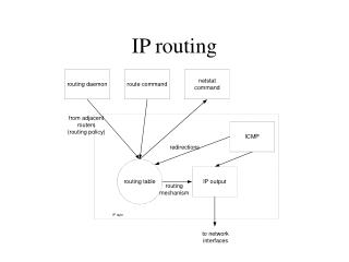
Introduction to IP Routing. Geoff Huston gih@telstra.net. Issues Covered. The IP Protocol Network Addresses Address Resolution Protocol (ARP) Routing Tables IP Routing Protocols Subnetting Routing Redirects Caveats. IP Addresses. 32 bit binary numbers

Introduction to IP Routing
E N D
Presentation Transcript
Introduction to IP Routing Geoff Huston gih@telstra.net
Issues Covered • The IP Protocol • Network Addresses • Address Resolution Protocol (ARP) • Routing Tables • IP Routing Protocols • Subnetting • Routing Redirects • Caveats
IP Addresses • 32 bit binary numbers • written as dot separated decimal bytes • address an INTERFACE, not a SYSTEM HOST 139.130.204.16 203.21.63.1 Serial Port Ethernet
IP Addresses • two level hierarchy • network prefix • host • all hosts within a common network prefix communicate without explicit routing tools visible to the network prefix 0 8 16 24 32 network prefix host identifier 203 . 23 . 15 . 4 255 . 255 . 255 . 0 IP address net mask
IP Addresses • Network Prefix Hierarchy • IANA • Regional Registry • Provider (s) • End Client • Broadcast Subnet (Physical Network) 202.0.0.0/7 APNIC Regional Registry 203.0.0.0/10 AARNet Provider Block 203.23.16.0/23 Fred’s web service End Client 203.23.16.0/24 Net A subnet 203.23.16.4/32 ns.fred.net.au host
When There is No Routing • systems on same physical subnet • no routing - transmission is via the media level protocols • must translate IP addresses into media (MAC) addresses to allow media level communication • Address Resolution Protocol (ARP) • if A wishes to communicate with B: • A broadcasts ARP Request for MAC address of B’s IP address across subnet • B arp caches A’s IP address to MAC address binding • B responds to A with ARP Reply • A arp caches B’s IP address to MAC address binding
Subnet IP MAC - IP addr binding • MAC Address Resolution techniques are media dependant • ethernet • Token Ring • FDDI • SMDS • Frame Relay • ATM
Minimalist Routing A B 139.130.204.4 139.130.204.5 139.130.204.1 139.130.204.0/26 G 203.23.15.1 203.23.15.5 203.23.15.0/24 C
Minimalist Routing • single path (gateway) through one system to other physical networks • eg. 139.130.204.1 (G) is manually defined as the “default” gateway for A within A’s IP forwarding table • an IP packet for C (203.23.15.5) from A is delivered as follows: • 203.23.15.5 is not on A's local network • so A arp’s for gateway G's Ethernet address • then pass the packet for 203.23.15.5 to G • G arp’s for C’s MAC address and delivers the packet to C
Routing • IP packets going from A to C have A's IP address as the source, and C's IP address as a destination • Ethernet packets travelling from A to G, enroute to C, have A's Ethernet address as the source and G's Ethernet address as the destination • A gateway: • must be on the same network • must have more than one network interface • is often a dedicated router, but can be a general purpose computing system with forwarding enabled
Multiple Gateways 192.107.107.1 A H 139.130.4.5 139.130.4.4 139.130.4.2 G C Other Networks 192.83.123.1 192.83.123.4
Multiple Gateways • use a Forwarding Table of (network, gateway) pairs • for A: • 139.130.0.0 139.130.4.2 (connected) • 192.83.123.0 139.130.4.5 (G) • 192.107.107.0 139.130.4.4 (H) • others 139.130.4.5 (H)
Routing Protocols • Forwarding Table entries are either defined manually (static routing), or updated dynamically by communicating with other systems • this dynamic interchange of routing information is specified by a routing protocol • it allows systems to take advantage of changes in the network topology without operator intervention • Routng protocols distribute network prefix values and associated attribtue values across the network • Routing protocols function through either • distributed computng model (distance vector) • parallel computing model (SPF)
Default Route • for routers connected to the Internet exchanging information about all connected networks is not desirable! (some38,000 network prefixes) • concept of a default network/route - packets for networks not listed in the routing table are sent to the "default" gateway • in previous example • gateway C had a link to "other networks" - it would be the default gateway for network 192.83.123.0 • G would be the default gateway for 139.130.0.0
RIP • still the most commonly used routing protocol is the Routing Information Protocol (RIP) (despite historical status) • simple to understand and operate • distance vector protocol
RIP operation • every 30 seconds, each RIP system broadcasts the list of network and metric paris within it's routing table to all networks to which it is connected to • each router that receives a RIP broadcast adds the networks contained within the message to its routing table (the gateway for these routing table entries is the system that sent the RIP message) provided that the network metric is lower than that of any existing entry for the network. • the use of the metric: • if a system receives two routes to the same network from different systems which one does it use ? • each route (network, gateway pair) is assigned a cost - RIP uses hop count as a metric • the route with the lowest metric is prefered
ICMP REDIRECTS • Auto insertion of host routes into the host’s forwarding table. • Both G and H have routes to network X. If A sends a packet destined for network X to H, then H will • forward the packet to G for delivery, and • send a redirect to A that tells A the system it was trying to communicate with is more efficiently reached via G. • A stores this information in its routing table
ICMP • Echo Request and Reply • Any host that receives an ICMP echo request message should respond with an echo reply • Useful for testing connectivity (ping application) • Unreachables • An ICMP message is sent to the originator of an IP packet if that packet cannot be forwarded • Most common cause for this is that the network or destination address is unreachable, ie. there was no entry in a routing table for the destination network
War Stories (Example) • Routing is not symmetric • X is a subnetted network • GW has a static route to Y via VAX • GW has a route to default via the AARNet link • VAX has a static route to Y via IBM#1 • VAX has a route to default via GW • IBM#1has static route to default via VAX • IBM#2 has static route to default via Y • Why could IBM #2 ping any system on the Internet, but IBM #1 could only ping hosts on network Y ? • Answer: Pings from IBM #1 have a source IP address on network X.2. GW could not return the pings to IBM #1 since it had no route to X.2
War Stories (Suggestions) • Be careful that you peer routes only with those you want to! • Be careful which routes you listen to • particularly if they claim to have a route to default! • filter all incoming route advertisements against a static sanity filter. • Do not play with the routing timers! • timers must be the same throughout a network • Just engineering a physical linkdoes guarantee that traffic will flow • some system somewhere must provide routing information about how to reach the newly connected network • Installing backup circuits is easy, making the routing work may not be • need a clear understanding of how the client networks want their traffic to flow before you can start making routing configuration changes