Fan Performance
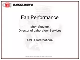
Fan Performance. Mark Stevens Director of Laboratory Services. AMCA International. Fan Testing for Air Performance. AMCA Standard 210. Piezometer Ring. Fan Static Pressure. Nozzles. Fan Airflow. Test Fan. Auxiliary Fan. AMCA 210 Test Results. 800. 2.5. 700. 2. 600. 500. 1.5.

Fan Performance
E N D
Presentation Transcript
Fan Performance Mark Stevens Director of Laboratory Services AMCA International
AMCA Standard 210 Piezometer Ring Fan Static Pressure Nozzles Fan Airflow Test Fan Auxiliary Fan
AMCA 210 Test Results 800 2.5 700 2 600 500 1.5 Power, H 400 Pressure, P 1 300 200 0.5 100 0 0 0 2 4 6 8 10 12 Air Flow, Q
) ) ) ( ( ( NC NC NC QC = Q N N N 2 PC = P 3 HC = H Fan Laws for Speed Change Q, Fan Airflow Rate P, Fan Pressure H, Fan Power
33% More H 10% More Q 10% Speed Change 800 2.5 700 2 600 500 1.5 Power, H 400 Pressure, P 1 300 200 0.5 100 0 0 0 2 4 6 8 10 12 14 Air Flow, Q
AMCA Standards 500-D & -L Piezometer Ring Nozzles Damper Pressure Drop Test Damper Damper Airflow Auxiliary Fan
Operating Point Fan Operating Point AMCA 500-D Test Results 700 600 500 400 Pressure, P 300 200 100 0 0 2 4 6 8 10 12 Air Flow, Q
Operating Point Speed Change 800 700 600 New Operating Point 500 New speed 400 Pressure, P 300 200 100 0 0 2 4 6 8 10 12 14 Air Flow, Q
Damper Opening 700 600 500 Operating Point 400 New Operating Point Pressure, P 300 New System 200 100 0 0 2 4 6 8 10 12 Air Flow, Q
System Effect • Installed duct configuration does not match tested duct configuration • Detrimental effect on fan air performance due to adverse flow conditions at the inlet or outlet of a fan
Piezometer Ring Fan Static Pressure Nozzles Fan Airflow Test Fan Auxiliary Fan Plenum Plenum Installation Type DDucted Inlet / Ducted Outlet Installed Fan
AMCA Catalog Ratings • “Performance certified is forinstallation type: • A: Free inlet, Free outlet” • B: Free inlet, Ducted outlet” • C: Ducted inlet, Free outlet” • D: Ducted inlet, Ducted outlet”
System Effect • Even when the tested duct configuration matches the installed duct configuration, improper duct design can introduce adverse flow conditions
Plenum Detailed Plenum Example
Detailed Plenum Example • Centrifugal Fan • Airflow Rate • 14.4 m3/s • Blast Area/Outlet Area • 0.6 • Velocity • 14.4 m/s Cutoff Blast Area Outlet Area
Detailed Plenum Example E-F duct friction at 5000CMH (Q) 747 Pa (duct design) E contraction loss-plenum to duct 50 Pa (part of duct system) E PS energy required to create velocity at E 125 Pa (part of duct system) D PV loss (also PT loss) at D as result of air velocity decrease 0 Pa PS does not change from duct to plenum at D C-D outlet duct on fan as tested 0 Pa -------------------- REQUIRED Fan PS 922 Pa
Detailed Plenum Example D-E duct friction at 5000CMH (Q) 747 Pa (duct design) D contraction loss-plenum to duct 50 Pa (part of duct system) D PS energy required to create velocity at D 125 Pa (part of duct system) B-C SEF 149 Pa B-C PV loss (also PT loss) at C as result of air velocity decrease 0 Pa PS does not change from duct to plenum at C ------------------ REQUIRED Fan PS 1071 Pa
Detailed Plenum Example Calculation of SEF of 149 Pa From AMCA Publication 210 N o 1 2 % 2 5 % 5 0 % 1 0 0 % D u c t E f f e c t i v e E f f e c t i v e E f f e c t i v e E f f e c t i v e D u c t D u c t D u c t D u c t From Figure 8.3 Outlet Duct B l a s t A r e a S y s t e m E f f e c t C u r v e O u t l e t A r e a 0 . 4 P R - S U W - - 0 . 5 P R - S U W - - 0 . 6 R - S S - T U - V W - X - - 0 . 7 S U W - X - - - - 0 . 8 T - U V W X - - - - 0 . 9 W - W W - X - - - - - - 100% Effective Duct Length 1 . 0 - - - - - - - - - -
Using line R from Figure 7.1 14.4 m/s
Plenum Example from AMCA 201 Assuming: • Use of the same fan for both systems • Can attain both operating points with a change in speed • The increased in power consumption to overcome System Effect is about 25% • (1071/922)0.5 = 1.08 (Fan Law for pressure) • 1.083 = 1.25 (Fan Law for Power)
Ducted FanFan as Tested C-D duct friction 750 Pa (duct design) A free inlet 0 Pa (no SEF) B-C outlet with straight duct attached for 2 or more diam. 0 Pa (no SEF) -------------------- REQUIRED Fan PS 750 Pa
Ducted FanExhaust System A Entrance loss-sharp edge duct 100 Pa (duct design) A-B Duct friction at 5000CMH 750 Pa (duct design) B SEF 1 (Elbow at Inlet) 150 Pa C SEF 2 (Obstruction) 50 Pa E SEF 3 (Abrupt Discharge) 150 Pa ------------------ REQUIRED Fan Ps 1200 Pa
Speed Changes • Before Increasing Speed • Check with the manufacturer for max safe operating speed • Determine expected power increase • Motor size • Electric Service • Expect more noise
Rules of Thumb • Minimum 2.5 duct diameters on Outlet • Minimum 3 to 5 duct diameters on Inlet • Avoid inlet swirl
Recommendations • Allow enough space in the building design to allow for appropriate fan connections to the system
Recommendations • Use allowances in the design calculations when space or other factors dictate less than optimum arrangement of the fan outlet and inlet connections
Recommendations • Include adequate allowance for the effect of all accessories and appurtenances on the performance of the system and the fan
Thank you AMCA International, Inc. 30 W. University Drive Arlington Heights, IL 60004 USA Tel: +1 847 394 0150 Fax: +1 847 253 0088 www.amca.org Mark Stevens - mstevens@amca.org