Download
1 / 78
850 likes | 3.21k Vues
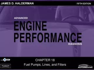
CHAPTER 18 Fuel Pumps, Lines, and Filters. OBJECTIVES. After studying Chapter 18, the reader will be able to: Prepare for ASE Engine Performance (A8) certification test content area “C” (Fuel, Air Induction, and Exhaust Systems Diagnosis and Repair).

E N D
CHAPTER 18 Fuel Pumps, Lines, and Filters
OBJECTIVES After studying Chapter 18, the reader will be able to: • Prepare for ASE Engine Performance (A8) certification test content area “C” (Fuel, Air Induction, and Exhaust Systems Diagnosis and Repair). • Describe the construction and operation of fuel tanks, lines and filters. • Describe how to check an electric fuel pump for proper pressure and volume delivery. • Explain how to check a fuel-pressure regulator. • Describe how to test fuel injectors. • Explain how to diagnose electronic fuel-injection problems.
Accumulator Baffle Check valve Delivery system Filter basket Gerotor Hydrokinetic pump Inertia switch Onboard refueling vapor recovery (ORVR) Peripheral pump Residual or rest pressure Roller cell Rotary vane pump Side-channel pump Turbine pump Vacuum lock Vapor lock Volatile organic compound (VOC) KEY TERMS
FUEL DELIVERY SYSTEM • Creating and maintaining a correct air–fuel mixture requires a properly functioning fuel and air delivery system. • Fuel delivery (and return) systems use many if not all of the following components to make certain that fuel is available under the right conditions to the fuel-injection system: • Fuel storage tank, filler neck, and gas cap • Fuel tank pressure sensor • Fuel pump • Fuel filter(s) • Fuel delivery lines and fuel rail • Fuel-pressure regulator • Fuel return line (if equipped with a return-type fuel delivery system)
FUEL TANKS • A vehicle fuel tank is made of corrosion-resistant steel or polyethylene plastic. • Some models, such as sport utility vehicles (SUVs) and light trucks, may have an auxiliary fuel tank. • Tank design and capacity are a compromise between available space, filler location, fuel expansion room, and fuel movement. • Some later-model tanks deliberately limit tank capacity by extending the filler tube neck into the tank low enough to prevent complete filling, or by providing for expansion room.
FUEL TANKS • Regardless of size and shape, all fuel tanks incorporate most if not all of the following features: • Inlet or filler tube through which fuel enters the tank • Filler cap with pressure holding and relief features • An outlet to the fuel line leading to the fuel pump or fuel injector • Fuel pump mounted within the tank • Tank vent system • Fuel pickup tube and fuel level sending unit
FUEL TANKS • TANK LOCATION AND MOUNTING • FILLER TUBES • PRESSURE-VACUUM FILLER CAP • FUEL PICKUP TUBE • TANK VENTING REQUIREMENTS
FIGURE 18–3 A view of a typical filler tube with the fuel tank removed. Notice the ground strap used to help prevent the buildup of static electricity as the fuel flows into the plastic tank. The check ball looks exactly like a ping-pong ball. FUEL TANKS
FIGURE 18–4 Vehicles equipped with onboard refueling vapor recovery usually have a reduced-size fill tube. FUEL TANKS
FIGURE 18–5 The fuel pickup tube is part of the fuel sender and pump assembly. FUEL TANKS
ROLLOVER LEAKAGE PROTECTION • All vehicles have one or more devices to prevent fuel leaks in case of vehicle rollover or a collision in which fuel may spill. • Variations of the basic one-way check valve may be installed in any number of places between the fuel tank and the engine. • The valve may be installed in the fuel return line, vapor vent line, or fuel tank filler cap.
ROLLOVER LEAKAGE PROTECTION • In addition to the rollover protection devices, some vehicles use devices to ensure that the fuel pump shuts off when an accident occurs. • Some pumps depend upon an oil pressure or an engine speed signal to continue operating; these pumps turn off whenever the engine dies. • On some air vane sensors, a microswitch is built into the sensor to switch on the fuel pump as soon as intake airflow causes the vane to lift from its rest position.
FIGURE 18–6 On some vehicles equipped with an airflow sensor, a switch is used to energize the fuel pump. In the event of a collision, the switch opens and the fuel flow stops. ROLLOVER LEAKAGE PROTECTION
FIGURE 18–7 Ford uses an inertia switch to turn off the electric fuel pump in an accident. ROLLOVER LEAKAGE PROTECTION
FUEL LINES • Fuel and vapor lines made of steel, nylon tubing, or fuel-resistant rubber hoses connect the parts of the fuel system. • Fuel lines supply fuel to the throttle body or fuel rail. • They also return excess fuel and vapors to the tank. • Depending on their function, fuel and vapor lines may be either rigid or flexible. • Fuel lines must remain as cool as possible. • If any part of the line is located near too much heat, the gasoline passing through it vaporizes and vapor lock occurs. • When this happens, the fuel pump supplies only vapor that passes into the injectors. • Without liquid gasoline, the engine stalls and a hot restart problem develops.
FUEL LINES • RIGID LINES • FLEXIBLE LINES • FUEL LINE MOUNTING • FUEL-INJECTION LINES AND CLAMPS • FUEL-INJECTION FITTINGS AND NYLON LINES • FUEL LINE LAYOUT
FIGURE 18–8 Fuel lines are routed along the frame or body and secured with clips. FUEL LINES
FIGURE 18–9 Some Ford metal line connections use springlocks and O-rings. FUEL LINES
FIGURE 18–10 Ford spring-lock connectors require a special tool for disassembly. FUEL LINES
FIGURE 18–11 Typical quick-connect steps. FUEL LINES
Just How Much Fuel Is Recirculated? • Approximately 80% of the available fuel-pump volume is released to the fuel tank bypassing the fuelpressure regulator at idle speed. As an example, a passenger vehicle cruising down the road at 60 mph gets 30 mpg. With a typical return-style fuel system pumping about 30 gallons per hour from the tank, it would therefore burn 2 gallons per hour, and return about 28 gallons per hour to the tank!
How Can an Electric Pump Work Inside a Gas Tank and Not Cause a Fire? • Even though fuel fills the entire pump, no burnable mixture exists inside the pump because there is no air and no danger of commutator brush arcing, igniting the fuel.
ELECTRIC FUEL PUMPS • The electric fuel pump is a pusher unit. • When the pump is mounted in the tank, the entire fuel supply line to the engine can be pressurized. • Because the fuel, when pressurized, has a higher boiling point, it is unlikely that vapor will form to interfere with fuel flow. • Most vehicles use the impeller or turbine pumps.
FIGURE 18–12 A roller cell-type electric fuel pump. ELECTRIC FUEL PUMPS
ELECTRIC FUEL PUMPS • POSITIVE DISPLACEMENT PUMP • HYDROKINETIC FLOW PUMP DESIGN • MODULAR FUEL SENDER ASSEMBLY • ELECTRIC PUMP CONTROL CIRCUITS • CHRYSLER • GENERAL MOTORS • FORD • PUMP PULSATION DAMPENING • VARIABLE SPEED PUMPS
FIGURE 18–13 The pumping action of an impeller or rotary vane pump. ELECTRIC FUEL PUMPS
FIGURE 18–14 An exploded view of a gerotor electric fuel pump. ELECTRIC FUEL PUMPS
FIGURE 18–15 A cutaway view of a typical two-stage turbine electric fuel pump. ELECTRIC FUEL PUMPS
Why Are Many Fuel-Pump Modules Spring-Loaded? • Fuel modules that contain the fuel pickup sock, fuel pump, and fuel level sensor are often spring-loaded when fitted to a plastic fuel tank. The plastic material shrinks when cold and expands when hot, so having the fuel module spring-loaded ensures that the fuel pickup sock will always be the same distance from the bottom of the tank.
FIGURE 18–16 A typical fuel-pump module assembly, which includes the pickup strainer and fuel pump, as well as the fuelpressure sensor and fuel level sensing unit. Why Are Many Fuel-Pump Modules Spring-Loaded?
FIGURE 18–17 A schematic showing that an inertia switch is connected in series between the fuel-pump relay and the fuel pump. ELECTRIC FUEL PUMPS
FIGURE 18–18 A typical fuel pulsator used mostly with roller vane-type pumps to help even out the pulsation in pressure that can cause noise. ELECTRIC FUEL PUMPS
FUEL FILTERS • Despite the care generally taken in refining, storing, and delivering gasoline, some impurities get into the automotive fuel system. • Fuel filters remove dirt, rust, water, and other contamination from the gasoline before it can reach the fuel injectors. • Most fuel filters are designed to filter particles that are 10 to 20 microns or larger in size.
FIGURE 18–19 Inline fuel filters are usually attached to the fuel line with screw clamps or threaded connections. The fuel filter must be installed in the proper direction or a restricted fuel flow can result. FUEL FILTERS • In addition to using several different types of fuel filters, a single fuel system may contain two or more filters. • The inline filter is located in the line between the fuel pump and the throttle body or fuel rail.
Be Sure That the Fuel Filter Is Installed Correctly • The fuel filter has flow direction and if it is installed backwards, the vehicle will most likely have a restricted exhaust (low power at higher engine speeds and loads). • All injectors, throttle body or port, are fitted with one or more filter screens or strainers to remove any particles (generally 10 microns or 0.00039 in.) that might have passed through the other filters. These screens, which surround the fuel inlet, are on the side of throttle-body injectors and are inserted in the top of port injectors.
FIGURE 18–20 The final filter, also called a filter basket, is the last filter in the fuel system. Be Sure That the Fuel Filter Is Installed Correctly
FUEL-PUMP TESTING • Fuel-pump testing includes many different tests and procedures. • Even though a fuel pump can pass one test, it does not mean that there is not a fuel-pump problem. • For example, if the pump motor is rotating slower than normal, it may be able to produce the specified pressure, but not enough volume to meet the needs of the engine while operating under a heavy load.
FUEL-PUMP TESTING • TESTING FUEL-PUMP PRESSURE • REST PRESSURE TEST • DYNAMIC PRESSURE TEST • FUEL-PUMP VOLUME TESTING
The Ear Test • No, this is not a test of your hearing, but rather using your ear to check that the electric fuel pump is operating. The electric fuel pump inside the fuel tank is often difficult to hear running, especially in a noisy shop environment. A commonly used trick to better hear the pump is to use a funnel in the fuel filter neck.
FIGURE 18–21 (a) A funnel helps in hearing if the electric fuel pump inside the gas tank is working. (b) If the pump is not running, check the wiring and current flow before going through the process of dropping the fuel tank to remove the pump. The Ear Test
FIGURE 18–22 The Schrader valve on this General Motors 3800 V-6 is located next to the fuel-pressure regulator. FUEL-PUMP TESTING
The Rubber Mallet Trick • Often a no-start condition is due to an inoperative electric fuel pump. A common trick is to tap on the bottom of the fuel tank with a rubber mallet in an attempt to jar the pump motor enough to work. Instead of pushing a vehicle into the shop, simply tap on the fuel tank and attempt to start the engine. This is not a repair, but rather a confirmation that the fuel pump does indeed require replacement.
FIGURE 18–23 The fuel system should hold pressure if the system is leak free. FUEL-PUMP TESTING
FIGURE 18–24 If the vacuum hose is removed from the fuelpressure regulator when the engine is running, the fuel pressure should increase. If it does not increase, then the fuel pump is not capable of supplying adequate pressure or the fuel-pressure regulator is defective. If gasoline is visible in the vacuum hose, the regulator is leaking and should be replaced. FUEL-PUMP TESTING
The Fuel-Pressure Stethoscope Test • When the fuel pump is energized and the engine is not running, fuel should be heard flowing back to the fuel tank at the outlet of the fuel-pressure regulator. If fuel is heard flowing through the return line, the fuel-pump pressure is higher than the regulator pressure. If no sound of fuel is heard, either the fuel pump or the fuel-pressure regulator is at fault.
FIGURE 18–25 Fuel should be heard returning to the fuel tank at the fuel return line if the fuel pump and fuel-pressure regulator are functioning correctly. The Fuel-Pressure Stethoscope Test
FIGURE 18–26 A fuel system tester connected in series in the fuel system so all of the fuel used flows through the meter which displays the rate-of-flow and the fuel pressure. FUEL-PUMP TESTING
Quick and Easy Fuel Volume Test • Testing for pump volume involves using a specialized tester or a fuel-pressure gauge equipped with a hose to allow the fuel to be drawn from the system into a container with volume markings to allow for a volume measurement. This test can be hazardous because of expanding gasoline.