Download
1 / 20
230 likes | 407 Vues
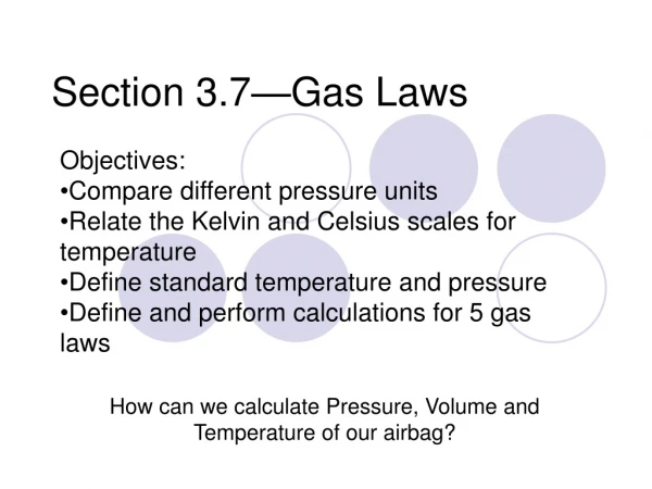
Section 3.7 Switching Circuits. What You Will Learn. Switching circuits. Electrical Circuits. Electrical circuits can be expressed as logical statements. T (true) represents a closed switch (or current flow). F (false) represents an open switch (or no current flow).

E N D
What You Will Learn • Switching circuits
Electrical Circuits • Electrical circuits can be expressed as logical statements. • T (true) represents a closed switch (or current flow). • F (false) represents an open switch (or no current flow). • In a series circuit the current can take only one path. • In a parallel circuit there are two or more paths the current can take.
Series Circuit • Case 1: Both switches are closed; that is, p is T and q is T. The light is on, T. • Case 2: Switch p is closed and switch q is open; that is, p is T and q is F. The light is off, F.
Series Circuit • Case 3: Switch p is open and switch q is closed; that is, p is F and q is T. The light is off, F. • Case 4: Both switches are open; that is, p is F and q is F. The light is off, F.
Series Circuit • Switches in series will always be represented with a conjunction ⋀. • In summary,
Parallel Circuit • Case 1: Both switches are closed; that is, p is T and q is T. The light is on, T. • Case 2: Switch p is closed and switch q is open; that is, p is T and q is F. The light is on, T.
Parallel Circuit • Case 3: Switch p is open and switch q is closed; that is, p is F and q is T. The light is on, T. • Case 4: Both switches are open; that is, p is F and q is F. The light is off, F.
Parallel Circuit • Switches in parallel will always be represented with a disjunction ⋁. • In summary,
Example 2: Representing a Switching Circuit with Symbolic Statements a. Write a symbolic statement that represents the circuit.
Example 2: Representing a Switching Circuit with Symbolic Statements Solution p and q are in parallel: p⋁ q q and r are in series: q⋀ r together we get: (p⋀ q) ⋁ (q ⋀ r)
Example 2: Representing a Switching Circuit with Symbolic Statements b. Construct a truth table to determine when the light will be on.
Example 2: Representing a Switching Circuit with Symbolic Statements Solution
Example 3: Representing a Symbolic Statement as a Switching Circuit Draw a switching circuit that represents [(p ⋀ ~q) ⋁ (r ⋁ q)] ⋀ s. Solution
Equivalent Circuits • Equivalent circuits are two circuits that have equivalent corresponding symbolic statements.
Equivalent Circuits • Sometimes two circuits that look very different will actually have the exact same conditions under which the light will be on. • The truth tables have identical answer columns.
Example 4: Are the Circuits Equivalent? Determine whether the two circuits are equivalent.
Example 4: Are the Circuits Equivalent? Solution p ⋁ (q ⋀ r) (p ⋁ q) ⋀ (p ⋁ r)
Example 4: Are the Circuits Equivalent? Solution The answer columns are identical.
Example 4: Are the Circuits Equivalent? Solution Therefore, p ⋁ (q ⋀ r) is equivalent to (p ⋁ q) ⋀ (p ⋁ r) and the two circuits are equivalent.