Innovative Oil Well Monitoring System for Abandoned Wells
380 likes | 527 Vues
This presentation explores a pioneering Oil Well Monitoring System designed to address the urgent need for monitoring over 27,000 permanently abandoned oil wells in the Gulf of Mexico. Four specialized engineering teams—Mechanical and Electrical—collaborated to develop a self-powered sensor system. The system aims to convert varying AC voltage to steady DC voltage, charge batteries, and operate in diverse environmental conditions, ensuring safety and operational efficiency for monitoring abandoned sites. Specifications include a wide input voltage range, cost-effective design, and high environmental resilience.

Innovative Oil Well Monitoring System for Abandoned Wells
E N D
Presentation Transcript
OILWELLMONITORINGSYSTEM Presented By:- Louis Bengtson KalebStunkard Jimit Shah
MOTIVATION • More than 27,000 oil wells permanently abandoned in the Gulf of Mexico. • Currently, there is no monitoring system available. • Four teams: • Buoy Team (Mechanical Engineering) • Bi-directional Turbine Team (Mechanical Engineering) • Sensor Team (Mechanical Engineering) • Electrical Team (Electrical Engineering)
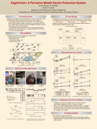
Turbine Ginlong Generator System Block Diagram INPUT CIRCUIT CONTROL PROCESSOR BUCK CONVERTER Sensor BATTERY CHARGING CIRCUIT Electrical System
OBJECTIVES • Efficiently convert varying AC voltage to steady DC voltage. • Be able to charge a battery that will supply the necessary output voltage to the sensors. • Must be self powered. • Components must be placed in an enclosure to be mounted on the buoy. • Must be able to work in high and low pressure environment. • Must be suitable for dry and wet conditions.
SPECIFICATIONS • Input RPM range: 90 to 125 RPM • Input Voltage range: 0VAC to 60VAC • Output Current: 1A • Output Voltage: 12VDC • Cost: Less than $2,000 • Efficiency: 85% • Operating Environments • Temperature: 25 to 110°F • Humidity: 100%
Input Circuit - KalebStunkard
BUCKCONVERTER &BATTERYCHARGINGCIRCUIT - Jimit Shah
Block Diagram DC Signal BUCK CONVERTER 0 - 60 V 15.6 V BATTERY CHARGER 13.8V BATTERY SENSORS Input Output
Buck Converter:TPS54260 – Step Down Converter • Wide Input Range • 3.5V to 60V • High Output Current • 0A to 2.5A • Enable Pin • Fixed Output Voltage • EVM available
TPS54260EVM Schematic Replaced Components: R6, C8, and C9
Battery Charger:BQ24450 – Integrated Charge Controller • Designed for Lead Acid Batteries. • Voltage and Current Regulation. • Optimization and maximization of battery capacity over temperature. • Ensure battery safety for charging at high temperature. • EVM available
BQ24450EVM Schematic Replaced Components: R7, and R11
Microcontroller - Louis Bengtson
Advantages of PIC Microcontrollers • PIC24FJ96GA010 • Extensive available parameters • Inexpensive • Programmable in C • Compatibility with development tools • Prospect of future improvements with reprogramming
Microcontroller Functions • Measure input voltage and battery voltage • Display voltage readings to LCD screen • Control the enable switch on the TPS54260EVM-597 DC-DC buck converter for hysteresis and over-voltage protection
Voltage Scaling • Input and Battery voltage were scaled down by voltage dividers. • Initially voltage divider produced loading effects at higher voltages. • LM324N op-amp was used as a unity gain buffer to prevent current feeding into microcontroller.
C Programming Language Code void main() { ADPCFG = 0xFFFF; // Configure AN pins as digital I/O TRISA = 0; // Initialize PORTA as output LATA = 1; // Set PORTA to one LCD_Init(); LCD_Cmd(_LCD_CURSOR_OFF); // LCD (cursor off) LCD_Cmd(_LCD_CLEAR); // Clear LCD text = "V in: "; // assign text to string text2 = "Batt V: "; while (1) { adc_rd = ADC1_read(10); // get ADC value – Input voltage adc_rd2 = ADC1_read(11); // get ADC value – Battery voltage LCD_Out(1,1,text); // print on LCD, row 1, collumn 1 LCD_Out(2,1,text2); // print on LCD, row 2, collumn 1 ch3 = 0; ch4 = 0; for(i=0;i<500;i++) { tlong = (long)adc_rd * 5000;// convert adc reading to mV tlong = (tlong / 1023); // 2^10 -> 0-5000mV ch = (tlong / 767); // extract 10 volts digit LCD_Chr(1,7,48+ch); // write ASCII digit at row1, collumn 7 ch = (tlong / 77) % 10; // extract volts digit LCD_Chr_CP(48+ch); // write ASCII digit at cursor point LCD_Chr_CP('.'); ch = (tlong / 8) % 10; // extract 0.1 volts digit LCD_Chr_CP(48+ch); // write ASCII digit at cursor point LCD_Chr_CP('V'); LCD_Chr_CP(' '); LCD_Chr_CP(' ');
C Programming Language Code Continued tlong2 = (long)adc_rd2 * 5000; // convert adc reading to mV tlong2 = tlong2 / 1023; // 2^10 -> 0-5000mV ch2 = tlong2 / 3800; // extract 10 volts digit LCD_Chr(2,9,48+ch2); // write ASCII digit row 2, collumn 9 ch2 = (tlong2 / 380) % 10; // extract volts digit LCD_Chr_CP(48+ch2); // write ASCII digit at cursor point LCD_Chr_CP('.'); ch2 = (tlong2 / 38) % 10; // extract 0.1 volts digit LCD_Chr_CP(48+ch2); // write ASCII digit at cursor point LCD_Chr_CP('V'); ch = (tlong / 800); // 10 volts digit ch3 = ch3 + ch; ch2 = (tlong / 80) % 10; // Volts digit ch4 = ch4 + ch2; Delay_ms(2); } // HYSTERESIS ch3 = (ch3 / 500); // Average 10 volts digit after 0.5 seconds ch4 = (ch4 / 500); // Average volts digit after 0.5 seconds if((ch3 == 5 && ch4 >= 5) || ch3 > 5) LATA = 0; // Disable the Buck over 55V if((ch3 == 1 && ch4 <= 5) || ch3 < 1) LATA = 0; // Disable the Buck under 15V if((ch3 == 2 && ch4 >= 5) || (ch3 > 2 && ch3 < 5)) LATA = 1; // Enable the Buck between 25V and 50V } }
Electrical Unit Buoy Turbine
Future Developments • GPS • Use of Sepic topology instead of Buck topology • Power Factor Correction • Code Optimization