Download
1 / 42
420 likes | 646 Vues
Optical mineralogy is a technique utilizing polarized light to examine minerals using a polarizing microscope. By observing textures, colors, cleavage, shapes, and other properties with a microscope, you can differentiate isotropic and anisotropic minerals. Learn about the components of a polarizing microscope and how to set it up for various microscopic observations. Discover the characteristics of light and properties related to wavelength, amplitude, and velocity. Understand the interference of light waves and the difference between polarized and non-polarized light in mineral analysis.

E N D
Optical Mineralogy • Technique utilizing interaction of polarized light with minerals • Uses a polarizing microscope • Oils - Grain mounts • Thin sections – rocks • Primary way to observe minerals • Important: • cheap, quick, easy • Only way to determine textures
Why use microscopes? • Visual properties for ID – e.g. texture • Color – may be variable • Cleavage (may not see, often controls shape) • Shape (depends on cut of mineral) • Only observable with microscope • Separate isotropic and anisotropic minerals and many other optical properties
Polarizing Microscope Ocular Bertrand lens Analyzer, upper polarizer, nicols lens Accessory Slot Objective Polarizer, typically oriented N-S
Slightly more modern version Trinocular head Reflected light source Analyzer, upper polarizer, nicols lens Accessory plate Objectives Vernier scale conoscope Internal light source, polarized
Four common settings for microscopic observations of thin sections: • Plane polarized light, analyzer (upper polarizer, nicols lens) out • Plane polarized light, analyzer in (cross nicols) • Conoscopic polarized light, bertrand lens in • Conoscopic polarized light, bertrand lens in, gypsum plate in accessory slot
Setting #1: No upper analyzer Setting #2: Upper analyzer inserted Quartz crystals in plane polarized light Same quartz crystals with analyzer inserted (cross polarizers aka crossed nicols)
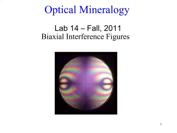
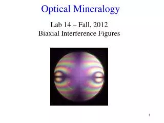
Setting # 3: Conoscopic polarized light, bertrand lens in, highest magnification • Setting #4: Conoscopic polarized light, bertrand lens in, gypsum plate in accessory slot, highest magnification
Characteristics of light • Electromagnetic energy • derived from excess energy of electrons • Energy released as electrons drop from excited state to lower energy shells – perceived as “light” • Particle, Wave or both • Particles = photons • For mineralogy, consider light a wave • Important wave interference phenomenon
Light as wave • Energy vibrates perpendicular to direction of propagation • Light has both electrical and magnetic energy • Two components vibrate perpendicular to each other • Electrical component interacts with electrical properties of minerals, e.g. bond strength, electron densities
Fig. 7-2 Electric vibration direction Magnetic vibration direction For mineralogy – we’ll only consider the electrical component
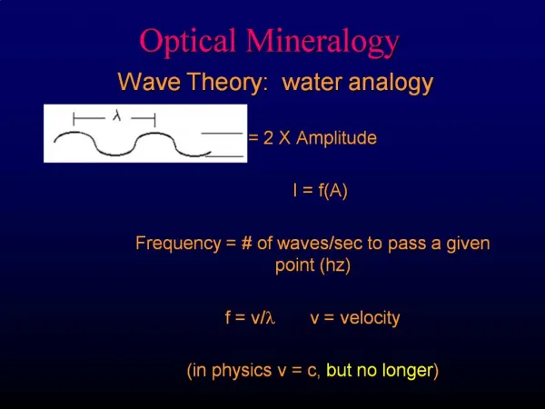
Properties of light Wavelength Amplitude Velocity
Relationship and units of properties • l = wavelength, unit = L, color of light • A = amplitude, unit = L, intensity of light • v = velocity, unit = L/t, property of material • f = frequency – e.g. how often a wave passes a particular point, unit = 1/t • f = v/l, frequency is constant, v and l variable
l (nm) Fig. 6-6 f (hertz) 1 Å Visable light spectrum 100 Å Full range of electromagnetic radiation 1 nm = 10-9 m
If two light waves vibrate at an angle to each other: • Vibrations interfere with each other • Interference creates a new wave • Direction determined by vector addition • Vibration directions of single wave can be split into various components • Each component has different vibration direction
Fig. 7-3 Note – two waves have the same v and l Electrical components only Two light waves A & B interfere to form resultant wave R One light wave X has a component V at an angle
Light composed of many waves • Wave front = connects same point on adjacent waves • Wave normal = line perpendicular to wave front • Light ray (Ray path) = direction of propagation of light energy, e.g. direction of path of photon • Note: wave normal and light ray are not necessarily parallel
Wave normal and ray path not always parallel Fig. 7-2c Wave front connects common points of multiple waves It is the direction the wave moves Ray path is direction of movement of energy, e.g., path a photon would take
Fig. 7-2d and e Wave normal and ray paths may be coincident Propogation of light through Isotropic material Wave normal and ray paths may not be coincident Propogation of light through Anisotropic material
Isotropic materials • Wave normals and ray paths are parallel • Velocity of light is constant regardless of direction in these minerals • Anisotropic materials • Wave normals and ray paths are not parallel • Velocity of light is variable depending on direction of wave normal and ray path • These difference have major consequences for interaction of light and materials
Polarized and Non-polarized Light • Non-polarized light • Vibrates in all directions perpendicular to direction of propagation • Occurs only in isotropic materials • Air, water, glass, etc. Fig. 7-4
Non-Polarized Light • Light vibrates in all directions perpendicular to ray path Multiple rays, vibrate in all directions Highly idealized – only 1 wavelength Fig. 7-4
Polarized light • Vibrates in only one plane • Generation of polarized light: • In anisotropic material, light usually resolves into two rays • Two rays vibrate perpendicular to each other • The energy of each ray absorbed by different amounts • If all of one ray absorbed, light emerges vibrating in only one direction • Called “Plane Polarized Light”
Anisotropic medium: light split into two rays. One fully absorbed Fig. 7-4b Polarized light vibrates in only one plane: “Plane-polarized light”
Polarization also caused by reflection: • “Glare” • Raybans cut the glare
Interaction of light and matter • Velocity of light depends on material it passes through • In vacuum, v = 3.0 x 10¹⁷ nm/sec = 3.0 x 10⁸ m/sec • All other materials, v < 3.0 x 10¹⁷ nm/sec
When light passes from one material to another • f = constant • If v increases, l also must increase • If v decreases, l decreases Vair > Vmineral f = v/l
Isotropic vs. Anisotropic • Isotropic geologic materials • Isometric minerals; also glass, liquids and gases • Electron density identical in all directions • Think back to crystallographic axes • Direction doesn’t affect the electrical property of light • Light speed doesn’t vary with direction • Light NOT split into two rays
Anisotropic geologic materials: • Minerals in tetragonal, hexagonal, orthorhombic, monoclinic and triclinic systems • Interactions between light and electrons differ depending on direction • Light split into two rays – vibrate perpendicular to each other • Light speed depends on direction of ray and thus vibration direction
Reflection and Refraction • Light hitting boundary of transparent material • Some reflected • Some refracted • Reflected light • Angle of incidence = angle of reflection • Amount controls luster
Fig. 7-6a For reflection: Angle of incidence, i = angle of reflection, r Light ray “reflective” boundary
Refracted light • Angle of incidence ≠ angle of refraction • Angle of refraction depends on specific property, Index of refraction, n • n = Vv/Vm • Vv = velocity in a vacuum (maximum) • Vm = velocity in material • Note – n is always > 1 • Big N means slow v • Little n means fast v
Angle of refraction given by Snell’s law Wave normal n=low, fast v N=big, slow v
Snell’s law works for isotropic and anisotropic material if: • are angles between normals to boundary • Direction is wave normal, not ray path
Measuring n important diagnostic tool • Not completely diagnostic, may vary within minerals • More than one mineral may have same n • n can’t be measured in thin section, but can be estimated
P. 306 – olivine information } Optical properties Indices of refraction {
Critical Angle - CA • A special case of Snell’s law • Light going from low to high index material (fast to slow, e.g. air to mineral) • Can always be refracted • Angle of refraction is smaller than angle of incidence
Light going from high to low index material • May not always be refracted • Light is refracted toward the high n material • At some critical angle of incidence, the light will travel along the interface • If angle of incidence is > CA, then total internal reflection • CA can be derived from Snell’s law
Fig. 7-7 All internal reflection High index to low index material: light cannot pass through boundary if angle of incidence > CA Critical angle is when angle of refraction = 90º N = high n = low
Dispersion • Material not always constant index of refraction • n = f(l) • Normal dispersion, within same material: • n higher for short wavelengths (blue) • n lower for long wavelengths (red)
Because of dispersion, important to determine n for particular wavelength • Typically n given for l = 486, 589, and 656 nm • Common wavelengths for sunlight