Optical Mineralogy
Optical Mineralogy. WS 2012/2013. Next week…. There is NO lecture REVISE!. Last week…. Indicatrix - 3-d representation of changing n in minerals Uniaxial indicatrix - ellipsoid of rotation tetragonal, hexagonal and trigonal crystal systems


Optical Mineralogy
E N D
Presentation Transcript
Optical Mineralogy WS 2012/2013
Next week…. There is NO lecture REVISE!
Last week…. • Indicatrix - 3-d representation of changing n in minerals • Uniaxial indicatrix - ellipsoid of rotation tetragonal, hexagonal and trigonal crystal systems • Uniaxial indicatrix can be positive (prolate or ‘rugby ball’) or negative (oblate or ‘smartie’) • Basal section circular o-ray (n) only isotropic • Random section ellipse o-ray and e’-ray (nn') intermediate polarisation colour • Principal section ellipse o-ray and e-ray (nn) maximum birefringence (n) highest polarisation colour
Last week…. • Polarisation colours - result of retardation(v) between o- and e-rays • = retardation = d ∙ n • Michel-Levy colour chart find max. polarisationcolour 30 m sectionsmeasurebirefringence (n) CHARACTERISTIC OF MINERAL • Coloursreportedby ORDER and COLOUR • ….fringecounting….
Crystal systems and symmetry The crystal systems are sub-divided by their degree of symmetry…. CUBIC >TETRAGONAL, HEXAGONAL, TRIGONAL>ORTHORHOMBIC, MONOCLINIC, TRICLINIC
The Optical Indicatrix • The optical indicatrix is a 3-dimensional graphical representation of the changing refractive index of a mineral; • The shape of the indicatrix reflects the crystal system to which the mineral belongs; • The distance from the centre to a point on the surface of the indicatrix is a direct measure of the refractive index (n) at that point; • Smallest n = X, intermediate n = Y, largest n = Z
Isotropic indicatrix nisconstantiseverydirection - isotropic minerals do not change the vibration direction of the light - no polarisation Sphere Indicatrix = 3-d representation of refractive index
Anisotropic minerals – Double refraction Example: Calcite • The incident ray is split into 2 rays that vibrate perpendicular to each other. • These rays have variable v (and therefore variable n) fast and slow rays • As n ∞ 1/v, fast = small n, slow =big n • One of the rays (the fast ray for calcite) obeys Snell’s Law - ordinary ray (no) • The other ray does not obey Snell’s law - extraordinary ray (ne) • Birefringence = Δn = | ne − no |
Retardation (Gangunterschied) • After time, t, when the slow ray is about to emerge from the mineral: • The slow ray has traveled distance d….. • The fast ray has travelled the distance d + ….. = retardation Fast wave with vf (lower nf) Slow wave with vs (higher ns) Slow wave: t = d/vs Fast wave: t = d/vf + /vair …and so d/vs = d/vf + /vair = d(vair/vs - vair/vf) = d(ns - nf) = d ∙ Δn d Mineral Polarised light (E_W) Retardation, = d ∙ Δn (in nm) Polariser (E-W)
Uniaxial Indicatrix All minerals belonging to theTRIGONAL, TETRAGONALand HEXAGONALcrystal systems have a uniaxial indicatrix…. This reflects the dominance of the axis of symmetry (= c-axis) in each system (3-, 4- and 6-fold respectively)….
Calcite n < n uniaxial negative Quartz n > n uniaxial positive
Uniaxial indicatrix – ellipsoid of rotation c=Z c=X n e n e n n o o b=X b=Z a=Z a=X optic axis ≡ c-axis NOTE: no = n nen n > n uniaxial positive (+) PROLATE or ‘RUGBY BALL‘ n < n uniaxial negative (-) OBLATE or ‘SMARTIE‘
Different slices through the indicatrix • Basal section Cut perpendicular to the optic axis: only n No birefringence (isotropic section) • Principal section Parallel to the optic axis: n & n Maximum birefringence • Random section n' and n n' is between n and n Intermediate birefringence • All sections contain n!
Crystal systems and symmetry The crystal systems are sub-divided by their degree of symmetry…. CUBIC >TETRAGONAL, HEXAGONAL, TRIGONAL>ORTHORHOMBIC, MONOCLINIC, TRICLINIC
The Biaxial Indicatrix (….the ‘potato’….) For orthorhombic, monoclinic and triclinic crystal systems: • The indicatrix is a triaxial ellipsoid with the axes X, Y, Z • The indicatrix has 3 principal refractive indices - n<n<n • The XZ plane (maximum n) is the OPTIC AXIAL PLANE • na = smallestn • nb= intermediate n • ng= largestn • Possiblevibrationdirections = • X, YandZ • X || na , Y || nb , Z || ng • na < na' < nb < ng' < ng
Biaxial indicatrix - principal section (XZ) ng OA OA = nb na = nb Cut ^ nb As n < n < n, there must be a point between n und n with n = n • This gives a circular section (= isotropic) • The OPTIC AXIS is perpendicular to the circular section • There must be 2 circular sections • optically BIAXIAL The optic axes lie in the XZ plane and are perpendicular to n • OPTIC AXIAL PLANE (max n)
The Bisectrix & 2V BZ 2VZ OA OA 2VX BX Angle between the optic axes 2V angle 2VX and 2VZ Bisector of this angle Bisectrix BX or BZ If the angle is acute acute bisectrix (2V < 90°) If the angle is obtuse obtuse bisectrix (2V > 90°)
Optical Sign (+ or -) Biaxial positive (+) defined as 2VZ < 90° …or… n closer to n than to n ‘RUGBY BALL’ like Biaxial negative (+) defined as 2VZ > 90° …or… n closer to n than to n ‘SMARTIE’ like
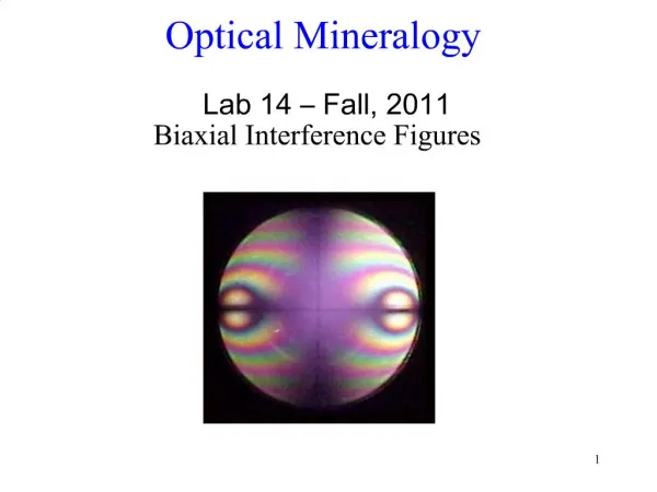
How do we know? We use CONOSCOPIC light to see whether a crystal is uniaxial or biaxial, positive or negative…. ….next two lectures….
Vibration directions & EXTINCTION In any random cut through an anistropic indicatrix, the privileged vibration directions are the long and short axis of the ellipse. We know where these are from the extinction positions….
Extinction Angle The EXTINCTION ANGLE is the angle between a linear feature in the crystal (a crystal edge, a cleavage plane, a twin plane) and the extinction position. The EXTINCTION ANGLE is (surprise, surprise) directly related to the CRYSTAL SYSTEM…. …more specifically, the angular relationship with the c-axis and the other crystallographic axes….
Symmetry and extinction angles In cubic minerals and those in the tetragonal, hexagonaland trigonal systems (= uniaxial minerals), the c-axis is at 90° to the other crystallographic axes…. STRAIGHT EXTINCTION
Symmetry and extinction angles This is also true of orthorhombic minerals STRAIGHT EXTINCTION For minerals in the monoclinic and triclinic systems (= biaxial), the c-axis is NOT at 90° to all the other crystallographic axes…. INCLINED EXTINCTION
Extinction Angle Extinction angle e = I – II = 29,5° I = 153,0° Only the MAXIMUM extinction angle is diagnostic of a mineral measure lots of grains II = 182,5°
Extinction Angle Only the MAXIMUM extinction angle is diagnostic of a mineral measure lots of grains
Tröger…. Look and work it out….
Retardation (Gangunterschied) • After time, t, when the slow ray is about to emerge from the mineral: • The slow ray has traveled distance d….. • The fast ray has travelled the distance d + ….. = retardation Fast wave with vf (lower nf) Slow wave with vs (higher ns) Slow wave: t = d/vs Fast wave: t = d/vf + /vair …and so d/vs = d/vf + /vair = d(vair/vs - vair/vf) = d(ns - nf) = d ∙ Δn d Mineral Polarised light (E_W) Retardation, = d ∙ Δn (in nm) Polariser (E-W)
Interference • Analyser forces rays to vibrate in the N-S plane and interfere. • Destructive interference (extinction): = k∙ k = 0, 1, 2, 3, … • Constructive interference (maximum intensity): = (2k+1) ∙ /2 k = 0, 1, 2, 3, …
Explanation of interference colours Example: a mineral with retardation of 550 nm in the diagonal position Retardation, 550 550 550 550 550 550 Wavelength, 400440489550629733 13/8l 11/4 l 11/8 l 1 l 7/8 l 3/4 l 550 nm is lost, other wavelengths will be partly or fully transmitted.
Retardation, 550 550 550 550 550 550 Wavelength, 400 440 489 550 629 733 13/8 l 11/4 l 11/8 l 1 l 7/8l 3/4 l No green (absorbed) red + violet purple interference colour Fig 7-7 Bloss, Optical Crystallography, MSA
Retardation, 800 800 800 800 800 800 800 Wavelength, 400 426 457 550 581 711 800 2l17/8l13/4l11/2l 13/8l1 1/8l1l No red or violet (absorbed) green interference colour Fig 7-7 Bloss, Optical Crystallography, MSA
Michel-Lévy colour chart birefringence(d) d = 0.009 d = 0.025 30 mm (0.03 mm) thickness of section lines of constant d retardation() first order second order third order ….orders separated by red colour bands….
Which order? - Fringe counting…. birefringence(d) d = 0.009 d = 0.025 30 mm (0.03 mm) lines of constant d retardation()