HRSG SIMULATION
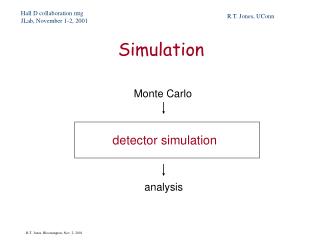
HRSG SIMULATION. V.Ganapathy. Knowing gas flow,temperature & analysis and steam parameters,establish HRSG temperature profiles,duty and steam flow. This is the design case,where for each surface we solve for:. What is HRSG Simulation. UA=Q/ T.

HRSG SIMULATION
E N D
Presentation Transcript
HRSG SIMULATION V.Ganapathy
Knowing gas flow,temperature & analysis and steam parameters,establish HRSG temperature profiles,duty and steam flow. This is the design case,where for each surface we solve for: What is HRSG Simulation UA=Q/ T In the off-design case,we know the new gas flow & temperature.It is desired to obtain the temperature profiles and steam flows. Calculation is tedious as surface area is indirectly known. Correct (UA) for effects of gas flow,temperature and analysis and solve for: Q=(UA)c T In typical design,we compute U and then A for each surface.In simulation we compute (UA) and hence there is no need to physically the HRSG in terms of tube size,fin density etc.Hence anyone familiar with heat balances can perform these studies. Consultants,plant engineers,project planners can use this method to evaluate HRSG performance without even knowing its size!They need not also contact a HRSG supplier!
Obtain design temperature profiles • Obtain off-design HRSG performance(unfired/fired) at different gas/steam conditions • Evaluate different gas turbines during initial project planning stages • Maximize energy recovery by modifying HRSG configuration • maximize energy recovery by adding secondary heat recovery such as deaerator,condensate heater • Evaluate field performance and relate it with HRSG performance guarantees • Write better HRSG specifications by knowing HRSG’s capabilities Applications of HRSG Simulation Ideal tool for cogen/combined cycle plant evaluation No need to physically design the HRSG! Saves time for consultants Limitation:Convective type surfaces with no external radiation
Note: This is the Design mode ..We cannot pre-select pinch and approach points in off-design mode! Pinch and Approach Points pinch point,F approach point,F a. evap type bare finned b.inlet gas temp,F 1200-1800 130-150 30-60 40-70 700-1200 80-130 10-30 10-40
Pinch and Approach points are selected in unfired mode at “Design” gas flow,exhaust gas temperature.These are called “design” pinch and approach points • Once selected,they fall in place in other cases of gas flow/inlet gas temperature/steam conditions,whether unfired or fired. • Pinch/approach points increase with inlet gas temperature • They cannot be arbitrarily selected Facts about Pinch and Approach Points -temperature cross can occur -low pinch point may not be physically feasible unless extended surfaces are used -affected by inlet gas temperature -economizer steaming is a concern ;suggest minimum approach at coldest ambient HRSG conditions -steam temperature can be achieved in fired conditions if it is achieved in unfired conditions • HRSG surfaces are determined once design pinch/approach points are selected
Exit gas temperature cannot be assumed as in conventional fired steam generators as temperature cross can occur.Looking at the superheater and evaporator,we have: WgxCpgx(tg1-tg3)=Ws(hso-hw2) (1) Looking at the entire HRSG, WgxCpgx(tg1-tg4)=Ws(hso-hw1) (2) [blow down and heat loss neglected] Why HRSG exit gas temperatures cannot be assumed Dividing (1) by (3) and neglecting effect of variations in Cpg with temperature,we have: (tg1-tg3)/ (tg1-tg4)= (hso-hw2)/ (hso-hw1)=K (3) For steam generation to occur and for a thermodynamically feasible temperature profile,two conditions must be met: If pinch and approach points are arbitrarily selected,one of these may not be met. Psig stm temp,F sat temp,F K exit gas,F 100 sat 338 .904 300 150 sat 366 .8704 313 250 sat 406 .8337 332 400 sat 448 .7895 353 400 600 450 .8063 367 600 sat 490 .7400 373 600 750 492 .7728 398 tg3>ts and tg4>tw1. Pinch=20F,approach=15 F,gas inlet=900 F,feed water=230 F
Example 1: Determine HRSG exit gas temperature when inlet gas temperature=900 F,steam press=100 psig.use 20 F pinch and 15 F approach points. Solution:K=0.904 sat temp=338 F.hence tg3=358F.tw2=323 F.(900-358)/(900-tg4)=0.904 or tg4=300 F Example 2: what is tg4 when steam press=600 psig and temp=750 F? Solution:K=0.7728.sat temp=492 F.tw2=477F.tg3=512 F.(900-512)/(900-tg4)=0.7728 or tg4=398 F.So 300 F stack temperature is not feasible! Example 3:Why can’t we obtain 300 F at 600 psig,750 F steam? Solution:K=0.7728 Let us compute tg3 from:(900-tg3)/(900-300)=0.7728 or tg3=436 F.This is called temperature cross! Example 4:What should be done to get 300 F stack temperature? Solution:Increase tg1 by firing.say tg1=1600 F.(1600-tg3)/(1600-300)=0.7728 or tg3=595 F and pinch=103 F. Example 5:If tg1=800F,what is tg4 at 100 psig sat? Solution:(800-358)/(800-tg4)=0.904 or tg4=312 vs 300 F when tg1 was 900F. Example 6:With 1600 F gas inlet,can we use 20 F pinch? Solution:(1600-512)/(1600-tg4)=0.7728 or tg4=192 F,which is below 230 F.Not feasible! That’s why pinch & approach points should not be selected in the fired mode!We have no idea in what range they can fall. Temperature calculations
The following procedure describes “Design” temperature profile calculations for HRSGs. Assume pinch and approach points. Saturation temperature ts is known by assuming a pressure drop through the superheater. tg3=ts+pp and tw2=ts-ap Energy absorbed by sh +evap = Temperature Profile Calculations Q12=WgxCpgx(tg1-tg3)xhl =Ws[(hso-hw2)+bd(hf-hw2)] .Ws is then computed. Q1=Superheater duty=Ws(hso-hv)=WgxCpgx(tg1-tg2) .Q1 and tg2 are thus obtained From above,Q2=(Q12-Q1)=evaporator duty is obtained. Economizer duty=Q3=Ws(1+bd)(hw2-hw1)=WgxCpg(tg3-tg4)xhl ; from this both Q3 and tg4 are obtained. hl=heat loss is on the order of 0.5 to 1 % bd=blow down varies from 1 to 7 % depending on feed water quality and boiler water conditions.
Using the concept that firing in a HRSG is 100 % efficient,we can evaluate the performance in fired case for estimation purposes. Example:160,000 lb/h of exhaust at 950 F enters a HRSG to generate 600 psig steam at 750 F from 230 F water.Determine unfired steam production and also burner duty,firing temperature and exit gas temperature when generating 35,000 lb/h of steam at 600 psig,750 F. Simplified HRSG Performance Solution:Using 25 F pinch and 20 F approach,compute energy absorbed by SH+evap=160,000x0.27x(950-517)x0.98=18.33 MM Btu/h=Ws(1378.9-455.4) or Ws=19,850 lb/h. Energy absorbed by HRSG=19,850x(1378.9-199.7)=23.4 MM Btu/h=160,000x0.98x0.268x(950-tg4) or tg4=393 F. Fired case: Energy absorbed by steam=35000x(1378.9-199.7)=41.27 MM Btu/h. Additional fuel energy required=(41.27-23.4)=17.87 MM Btu/h.Oxygen consumed=17.87x10⁶/(160000x58.4)=1.91 % So there is plenty of oxygen left. Firing temperature=17.87x106=160000x0.3x(T-950) or T=1322 F Exit gas temperature=1322-41.27x10⁶ /(160000x.275x.98)=364 F
DESIGN • unfired • establishes configuration • establishes surface areas indirectly • only one case • zero desuperheater spray • pinch and approach points selected • zero economizer steaming Design & Off-design calculations • OFF-DESIGN • unfired/fired/fan mode/combination • several cases possible • computes desuperheater spray • pinch and approach points computed • economizer steaming possible • WHATIF STUDIES • steam pressure variations • firing temperature restrictions • effect of fuels • performance testing • effect of gas turbine load • variations in ambient temperature
The energy transferred to the evaporator is given by: Q=WgCp(T1-T2)=UST=US (T1-T2)/ln[(T1-ts)/(T2-ts)] ; simplifying, ln[(T1-ts)/(T2-ts)]=US/WgCp . In a fire tube boiler,U Wg0.8. For a water tube boiler,U Wg0.6 ,neglecting the effects of temperature. Then, Wg0.2ln[(T1-ts)/(T2-ts)]=K1 for a fire tube boiler and Wg0.4ln[(T1-ts)/(T2-ts)]=K2 for a water tube boiler A simple example of simulation Example: A water tube boiler is designed to generate steam at 250 psig with 100,000 lb/h of flue gas at 1000 F.Exit gas temperature is 500 F.What is the exit gas temperature when 90,000 lb/h of flue gas enters the boiler at 970 F and steam pressure is 200 psig? Solution: First compute K2 using design conditions... 1000000.4ln[(1000-406)/(500-406)]=184.4=K2 In the off-design case,900000.4ln[(970-388)/(T2-388)]=184.4 or T2=473 F.Duty and steam generation may be computed from this. [406 and 388 F are saturation temperatures corresponding to 250 and 200 psig respectively.]
Example of a HRSG simulation Example:140,000 lb/h of turbine exhaust gases at 980 F enter a HRSG generating sat steam at 200 psig.Determine the steam generation and temperature profiles if feed water temperature is 230 Fand blow down=5%. Solution: Let us choose a pinch point of 20F and approach of 15 F.Sat temperature=388F. Gas temperature leaving evaporator=408 F and water temperature entering it is 373 F.Evaporator duty=140000x.99x.27x(980-408)=21.4 Mm Btu/h. [ 1% heat loss and average specific heat of 0.27 Btu/lbF is assumed] Enthalpy absorbed in evaporator=1199.3-345+.05x(362.2-345)=855.2 Btu/lb [1199.3,345 and 362.2 are enthalpies of sat steam,water entering evaporator and saturated water respectively]. Hence steam generation=21.4x10⁶/855.2=25,000 lb/h Economizer duty=25000x1.05x(345-198.5)=3.84 Mm Btu/h .gas temperature drop=3840000/(140000x.253x.99)=109 F.Hence exit gas temperature=408-109=299 F
Off-design Performance Simulate the HRSG performance with a 165,000 lb/h of gas flow at 880 F.Steam pressure =150 psig. Using the model for evaporators discussed elsewhere,ln[(980-388)/(408-388)]=Kx140000-0.4 or K=387.6 Under new conditions: ln[(880-366)/(Tg-366)]=387x165000-0.4 =3.1724 or Tg=388 F.Evaporator duty=165000x.99x.27x(880-388)=21.7 MM Btu/h In order to determine the steam flow,the feed water temperature to evaporator must be known.Try 360 F.Then steam flow=21.7x10⁶/[1195.7-332)+.05x(338.5-332)]=25,110 lb/h. Economizer duty(assumed) Qa=25110x1.05x(332-198.5)=3.52MM Btu/h.Compute (US)d=Q/T for economizer based on design conditions. Q=3.84x10⁶ T =[(408-373)-(299-230)]/ln[(69/35)]=50 F.(US)d=3840000/50=76800. Correct this for off-design case. (US)p=(US)dx(165000/140000).65=85200.The effect of variations in gas temperature is minor and not considered. The energy transferred =(US)p xT. Based on 360F water exit temperature,the economizer duty=3.52MM Btu/h and gas temperature drop=3520000/(165000x.99x.253)=85 F or exit gas =388-85=303 F.T=[(303-230)-(388-350)]/ln[(73/28)]=47 F or transferred duty=85200x47=4.00 Mm Btu/h.As this does not match the assumed value of 360F and duty ,another iteration is required. It can be shown at 366 F,the balance is obtained.
Superheater performance Performance of a superheater is obtained from: Q=(US)pT T=[(Tg1-ts2)-(Tg2-ts2)]/ln[(Tg1-ts2)/(Tg2-ts2)] (US)p is obtained from design (US) values as follows: (US)p=Wg0.65FgK1(Ws/Wsd)0.15where K1=a constant obtained from design case = Q1/(T Wg0.65Fg) where Fg = (Cp0.33k0.67/m0.32).Basically we are correcting for the effects of: 1.Gas flow 2. gas analysis, gas temperature and hence gas properties, which is significant if the superheater operates say in unfired and fired modes. Similar constants K2,K3 may be evaluated for evaporator and economizer. Example:In design mode, gas flow=150,000 lb/h.Gas in=900F and leaving SH=842F. steam flow=18510 lb/h.steam pressure=450 psig. steam in=460F,out=650F.duty=2.34 MM Btu/h Cp=.273,m=.0826 ,k=.029. Fg=.2730.33x.0290.67/.08260.32=0.135.T=[(842-460)-(900-650)]/ln[(842-460)/(900-650)] = 311F.Hence K1=2.34x10⁶/(311x.135x1500000.65) =24.1 Off-design:steam flow=18050 lb/h,gas flow=165000,gas in=840F.steam pressure=450 psig.Let exit steam temp=640F.Duty=18050x(1325-1204.4)=2.177MM Btu/h. Exit gas=840-2177000/165000/.99/.271=791F. Since gas temperatures are close, Use same Fg=0.135. (US)p=1650000.65x0.135x24.1x(18050/18510)0.15=7974. T=[(840-640)-(791-460)]/ln[(840-640)-(791-460)]=260F. Hence Qt=7974x260=2.074MM Btu/h. This is close to the assumed value, else another iteration would be required. The NTU method may also be used here by using the new US term.
Performance may be obtained even if HRSG geometry is unknown using simulation concept. HRSG Performance Calculations
Why are HRSGS inefficient? • Low steam/gas ratios • Low inlet gas temperatures(900 F vs 3300 F) • Temperature profiles depend on steam pressure and temperature • Higher the pressure,lower the steam generation • Higher the steam temperature,lower the steam generation (and higher the exit gas temperature)
Design with lower pinch and approach points • Use of secondary surfaces such as condensate heater,heat exchanger,deaerator • Consider multiple pressure HRSG • Use supplementary firing • Optimize temperature profiles by rearranging surfaces ImprovingHRSG Efficiency
Improving HRSG performance Bottom line is to lower the exit gas temperature!
Knowing gas flow,temperature,analysis and steam parameters,establish HRSG temperature profiles,duty and steam flows.In the design case,solve for:UA=Q/T.In the off-design case knowing the new gas parameters,use the NTU method to establish performance using Q=(UA)T.Correct for UA using new gas parameters. We do not have to compute U. Hence there is no need to know the tube size,fin details,HRSG mechanical data;anyone can perform such calculations and evaluate HRSG performance in unfired,fired modes,evaluate burner duty,optimize temperature profiles,predict part load performance,review performance different gas turbines... HRSG simulation
HRSG Temperature profile HP stage is followed by LP section. Not a very efficient design
HRSG Temperature profile Using common Economizer concept,we improve energy recovery
100 % load Why Steaming occurs in HRSG Economizers
HRSG performance at Low Load HRSG performance at 40 % load. Note steaming in economizer and also the high exit gas temperature.
Effect of ambient temperature on HRSG performance Multiplication factor on steam flow is 0.1
Evaluating HRSG performance HRSG performance is evaluated at different gas flow,exhaust temperature conditions to see if the performance is reasonable.
Evaluating HRSG performance Design basis
Evaluating Operating Data Note:Actual steam flow is 68,700 lb/h and exit gas temperature is 380 F,while it should have been about 364 F.Hence further evaluations are necessary to check if HRSG design is adequate. The gas flow was estimated based on steam duty and inlet/exit gas temperatures.
TWO OR SINGLE PRESSURE HRSG-case 1 We are trying to see if a 2 pressure HRSG is required. Customer wants about 40,000 kg/h,30 kg/cm2 steam and 3000 kg/h steam at 6 kg/cm2 in fired mode and about 3500 kg/h LP steam in unfired mode,which is taken off the drum and pressure reduced..
Two or Single pressure HRSG-case 2 HRSG makes 40,000 kg/h HP steam at 400 C and 30 kg/cm2 and 3000 kg/h steam is taken off the drum for process and pressure reduced to 6 kg/cm2
Two or Single pressure HRSG-case 3 Here we have a dual pressure HRSG.
Two or Single Pressure HRSG?case 5 Here we see what happens if LP steam pressure were 3 instead of 6 kg/cm2
Two or Single Pressure HRSG?-case 6 Note the stack gas temperature with lower LP steam pressure.
Summary -two or single pressure? It may be seen that as long as the HRSG operates in the fired mode,the single pressure system has the same performance as the dual pressure unit when process LP steam is at 6 kg/cm2a,thus saving lot of expenditure, field costs,operational costs etc. A pressure reducing station replaces a complete LP evaporator,which could cost several hundred thousand dollars.If the LP steam pressure were different,then the outcome will be different.When process steam is at 3 kg/cm2a,then dual pressure looks attractive as seen in columns 5 and 6.HP steam is at 30 kg/cm2a.So there is an optimum LP pressure below which multiple pressure is justified. We cannot simply go for dual pressure without doing this analysis. If the HRSG runs more often in unfired mode,then a dual pressure may be warranted even at 6 kg/cm2
Effect of Exhaust gas analysis ABOVE: TYPICAL EXHAUST GAS. BELOW: WITH STEAM INJECTION. Note the difference in steam generation
HRSG temperature profiles Q 1: Exhaust gas flow is 100,000 kg/h at 550 C. % volume co2=3,h2o=7,h2o=75,o2=15. Steam at 60 kg/cm2a and 450 C is required. Feed water is at 110 C and blow down=1 %. Using say 10 C pinch and approach, arrive at the HRSG temperature profiles and steam generation. Q 2:Repeat the calculation at 10 kg/cm2a for saturated as well as superheated steam and discuss the findings. If pinch and approach increase by 5 C, 10 C, how much duty we lose and also the steam generation for Q 1 above? Table shows enthalpy in btu/lb vs temperature. If gas flow changes to 80,000 kg/h and steam pressure to 45 kg/cm2a in operation, what is the HRSG performance, duty, steam temperature and ASME efficiency? ASME efficiency=energy absorbed by steam/water/fluids or duty/(gas flow x enthalpy+fuel input on LHV basis)
EFFECT OF PART LOAD AND HIGH LOAD What are the effects of part load operation of gas turbine on HRSG and effect of supplementary firing? Discuss.
MULTIPLE PRESSURE HRSG HRSG performance at part loads
HRSG WITH REHEATER Module 1 2 3 4 5 6 7 8 9 10