Download
1 / 98
1.14k likes | 1.83k Vues
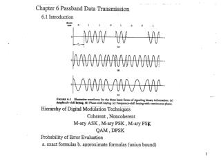
BER of BPSK. Figure 6.3 Signal-space diagram for coherent binary PSK system. The waveforms depicting the transmitted signals s 1 ( t ) and s 2 ( t ), displayed in the inserts, assume n c 2.

E N D
BER of BPSK Figure 6.3 Signal-space diagram for coherent binary PSK system. The waveforms depicting the transmitted signals s1(t) and s2(t), displayed in the inserts, assume nc 2.
Figure 6.3 Signal-space diagram for coherent binary PSK system. The waveforms depicting the transmitted signals s1(t) and s2(t), displayed in the inserts, assume nc 2.
Generation and Detection of Coherent BPSK Figure 6.4 Block diagrams for (a) binary PSK transmitter and (b) coherent binary PSK receiver.
Generation and Detection of Coherent BPSK si1 odd See Table 6.1 even si2 Figure 6.8 Block diagrams of (a) QPSK transmitter and (b) coherent QPSK receiver.
, g(t) denotes the symbol shaping function. The baseband QPSK PSD equals the sum of the inphase and quadrature PSD
Figure 6.7 (a) Input binary sequence. (b) Odd-numbered bits of input sequence and associated binary PSK wave. (c) Even-numbered bits of input sequence and associated binary PSK wave. (d) QPSK waveform defined as s(t) si1f1(t) si2f2(t).
Offset QPSK ( Reducing Carrier Amplitude Change) Figure 6.10 Possible paths for switching between the message points in (a) QPSK and (b) offset QPSK.
p/4 –shifted QPSK Two ordinary QPSK constellations Figure 6.11 Two commonly used signal constellations of QPSK; the arrows indicate the paths along which the QPSK modulator can change its state.
Figure 6.14 Illustrating the possibility of phase angles wrapping around the positive real axis.
Figure 6.13 Block diagram of the p/4-shifted DQPSK detector.
Figure 6.15 (a) Signal-space diagram for octaphase-shift keying (i.e., M 8). The decision boundaries are shown as dashed lines. (b) Signal-space diagram illustrating the application of the union bound for octaphase-shift keying.
Figure 6.16 Power spectra of M-ary PSK signals for M 2, 4, 8.
QAM Cross Constellation M=2nwhere n is odd (e.g., 5,7,…) Figure 6.18 Illustrating how a square QAM constellation can be expanded to form a QAM cross-constellation.
BFSK has a two-dimensional signal space Figure 6.25 Signal-space diagram for binary FSK system. The diagram also includes two inserts showing example waveforms of the two modulated signals s1(t) and s2(t).
Generation and Detection of Coherent BPSK Figure 6.26 Block diagrams for (a) binary FSK transmitter and (b) coherent binary FSK receiver.