Download
1 / 11
200 likes | 659 Vues
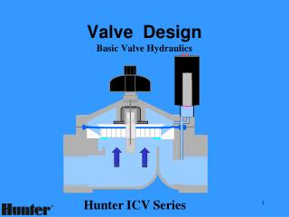
Figure 22.1 Typical vacuum-operated EGR valve. The operation of the valve is controlled by the computer by pulsing the EGR control solenoid on and off. Figure 22.2 When the EGR valve opens, exhaust flows through the valve and into passages in the intake manifold.

E N D
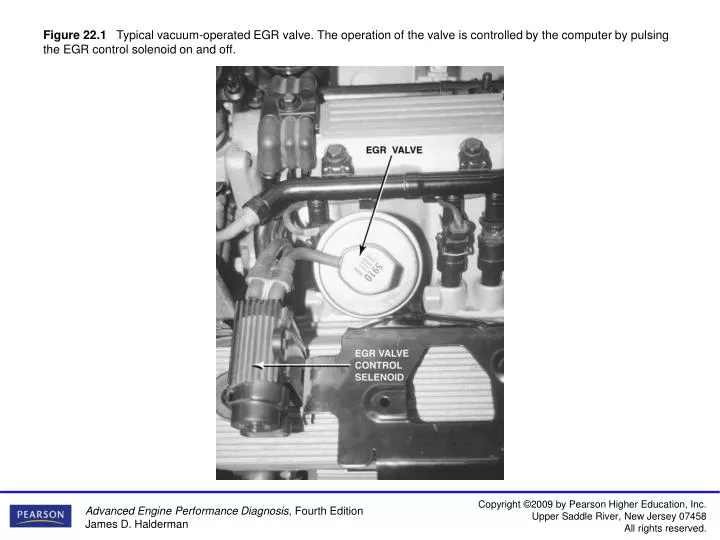
Figure 22.1Typical vacuum-operated EGR valve. The operation of the valve is controlled by the computer by pulsing the EGR control solenoid on and off.
Figure 22.2When the EGR valve opens, exhaust flows through the valve and into passages in the intake manifold.
Figure 22.3Back pressure in the exhaust system is used to close the control valve, thereby allowing engine vacuum to open the EGR valve.
Figure 22.4 An EGR valve position sensor on top of an EGR valve.
Figure 22.5An integrated EGR valve system showing the pintle-position sensor and vacuum diaphragm.
Figure 22.6This 3800 V-6 uses three solenoids for EGR. A scan tool can be used to turn on each solenoid to check if the valve is working and if the exhaust passages are capable of flowing enough exhaust to the intake manifold to affect engine operation when cycled.
Figure 22.8The EGR valve pintle is pulse-width modulated and a three-wire potentiometer provides pintle-position information back to the PCM.
Figure 22.10An OBD-II active test. The PCM opens the EGR valve and then monitors the MAP sensor and/or engine speed (RPM) to meet acceptable values.
Figure 22.11Removing the EGR passage plugs from the intake manifold on a Honda.