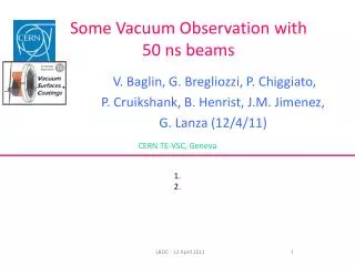
Vacuum Observation
Vacuum Observation. G. Bregliozzi (27/09/11 ). CERN TE-VSC, Geneva. ALICE Background ID 800: ZDC Detector TDI2L & TDI8R ATLAS, CMS and LHCb Summary. G. Bregliozzi - LBOC – 27 th of September 2011. ALICE: Vacuum layout. ALICE Cavern Layout: Q1 – Q1. A1R2.X. B1L2.X. A1L2.X.

Vacuum Observation
E N D
Presentation Transcript
Vacuum Observation G. Bregliozzi (27/09/11) CERN TE-VSC, Geneva • ALICE Background • ID 800: ZDC Detector • TDI2L & TDI8R • ATLAS, CMS and LHCb • Summary G. Bregliozzi - LBOC – 27th of September 2011
ALICE Cavern Layout: Q1 – Q1 A1R2.X B1L2.X A1L2.X VGI.220.1R2.X IP2.X VGI.220.1L2.X VGPB.190.1L2 For the installation drawing layout: https://lhc-div-miwg.web.cern.ch/lhc-div-miwg/Main_Pages/new_frame%20miwg_icl.htm ALICE Vacuum Instrumentations: Drawings IP2.X A1L2.X B1L2.X A1R2.X
ALICE Extended Tunnel Layout: D2 – D1 Vacuum Sector A4L2.X TDI ITL2 D2 VGPB.231.4L2 VGPB.123.4L2 VGI.514.4L2 ID 800 mm Vacuum Chamber Recombination chamber Vacuum Sector A4R2.X ITR2 D2 TCT + TCL VGI.514.4R2 VGPB.123.4R2 ID 800 mm Vacuum Chamber Recombination chamber
ALICE Cavern Pressure Distribution Before Technical Stop 4 10-7 mbar Cryo loss 10-11 mbar • IP: Maximum Pressure VGPB.190.1L2.X: 5·10-10 mbar
ALICE Cavern Pressure Distribution After Stop 4 10-7 mbar 10-11 mbar • IP: Maximum Pressure VGPB.190.1L2.X: 5·10-10 mbar
Summary D2- D1: Pressure Distribution Before Technical Stop 4 10-5mbar Highest pressure recorded at 80 m left from the IP in the TDI: VGPB.231.4L2.X 5·10-8 mbar 1·10-8 mbar Fills with ALICE detector partially ON 10-12mbar • Transient in the VGI (Light blue curve) at 108 m from the IP: both side
Summary D2- IT: Pressure Distribution after Technical Stop 10-5mbar Highest pressure recorded at 108 m right from the IP in the ID800 Chamber: VGPB.514.4R2.X Pressure dominated by the TDI Fills with ALICE detector ON 10-12mbar • Pressure in the TDI is equal as before the technical stop
Pressure at 3.5 TeV before collision: Before and After technical stop 4 Practically no pressure variation before and after the technical stop
ID800 vacuum ChambersIntensity Threshold for Electron Cloud Transient in the VGI at 108 m from the IP: both side 304 mA 321 mA 304 mA Fill 2037 Fill 2040
Pressure in the ID800 Vacuum Chambers Before Technical Stop 4 • Pressure taken (max) at 3.5 TeV before starting collision • Linear dependence with the beam current: Electron cloud symptom
Pressure in the ID800 Vacuum ChambersAfter Technical Stop 4 Constant Increase of Bunch Intensity form 1.3E11 up 1.38E11 p/b Despite increase in beam current (bunch intensity) Decrease of Pressure
Normalized Pressure to Beam Current ID800 Vacuum Chambers Conditioning Effects
Comparison of Beam ScrubbingID 800 mm and LSS7 during April 2011 Both gauges decrease of factor 4 after 30 h Pressure decrease in LSS2 is behaving the same as the pressure decrease due to beam scrubbing performed during MD in April in LSS7
Secondary electron 5 eV KeV Electron Cloud Build Up Mechanism LOST LOST Photoelectron 200 eV Secondary electron 10 eV Photoelectron 200 eV Photoelectron 200 eV + + + Secondary electron 5 eV 5 ns 7.5 m 25 ns Beam direction After F. Ruggiero, Chamonix X workshop
Electron cloud: Vacuum pressure rise • Vacuum cleaning: • Dose effects due to the electron bombardments which produce a decrease of the electron desorption yield, h, the number of gas molecules desorbed from the surface of the beam vacuum pipe by the primary electron. • Beam Scrubbing: • Dose effects due to the electron bombardments which produce a reduction of the secondary electron yield, d, the number of secondary electron generated by the primary electron. • Vacuum pressure rise • Electron stimulated desorption (ESD) • Multipacting length • Effective pumping speed
Vacuum Cleaning and Beam Scrubbing:Electron Dose J. Gómez-Goñi and A.G. Mathewson. J. Vac. Sci. Technol. A, vol. 15, No. 6, Nov/Dec 1997, p 3093
Installation of Electron Cloud Suppressor in Conical Transition of ZDC Vacuum Chambers This week end 950 m of cable around the conical chambers located at the extremity of the ID800 mm vacuum chambers of vacuum sector A4R2.C were installed: 1 layer The solenoid in LSS2R are powered to 5A: Apparently not sufficient magnetic field to suppress the formation of secondary electrons.
TDI LSS2L before Technical Stop 5·10-8 mbar 1.0·10-8 mbar Maximum pressure increase was 5·10-8 mbar. Pressure increase during the injection due to electron cloud After about 2 h of stable beam, pressure increase due to heating effects.
TDI LSS2L after Technical Stop 3.5·10-8 mbar 1.0·10-8 mbar Maximum pressure increase was 3.5·10-8 mbar. Pressure increase during the injection due to electron cloud After about 2 h of stable beam, pressure increase due to heating effects.
TDI LSS2L and LSS8R Both TDIs have the same behavior
Example of TDI in LSS8R • Starting from fill 2092 (1.29E11 p/b) a pressure increases are seen at TDI about 1h-2h after machine full • Temperature increases from 8 to 17 deg are observed at TDI extremities: measurements done externally. The temperature internally is higher.
What is the effects of the heating in the vacuum? 20h From room temperature to 100˚C the outgassing increase of factor ≈100 From room temperature to 50˚C the outgassing increase of factor ≈10 Data from P. Chiggiato The constant increase of bunch intensity before and after the technical stop are producing an heating effect in the TDI: HOM. Possible mitigations: 1) Add ventilator externally: reduce outgassing (possibly not sufficient) 2) Increase bunch length and/or decrease bunch intensity (to be defined by impedance experts)
ATLAS Cavern : Q1 – Q1 Synchrotron Radiation Beam Collision Q1 At 18 m from IP Maximum Pressure at Q1: 1·10-9 mbar Maximum Pressure at18 m from IP: 5·10-11 mbar Fill 2155
CMS Cavern: Q1 – Q1 Beam Collision Electron Cloud At 18m from IP During collision pressure quite constant in all IP: 5·10-10 mbar At 18 m right: pressure function of beam parameters: orbit, emittance,… Fill 2155
CMS Cavern: Q1 – Q1 The pressure reading at 18 m right of the IP is very sensitive to beam parameters variation Same bunch intensity – Same filling patterns 1·10-6 mbar 2·10-9 mbar Fill 2158 Fill 2157
LHCb Cavern Synchrotron Radiation Electron Cloud VELO Q1 Maximum Pressure in the VELO: 4·10-9 mbar Maximum Pressure at the Q1: 4·10-10 mbar Fill 2155
Vacuum Observation Summary • In ALICE Experiments: from Q1 to Q1: • No variation compared to the technical stop. • All the vacuum gauges are in the 10-10 mbar range. • LSS2: From Q4 to Inner Triplet: • The pressure in the ZDC vacuum chambers is decreasing: Vacuum cleaning and scrubbing is effective to decrease the effects of electron cloud. • TDI LSS 2 and LSS8: • During beam injection pressure increases due to electron cloud and then a further pressure increase is registered: Thermocouples installed externally to the TDI shows an increase of temperature up to DT of 17˚C: thermal outgassing is responsible for this pressure increase • In CMS at 18m right of the IP: • Pressure level variation is sensitive to beam parameters: few order of magnitude.