Effects of Draft EC 1130-2-xxxx on Acoustic Clearance Surveys in Navigation Projects
This presentation by the Harbor Safety Committee explores the potential impacts of Draft EC 1130-2-xxxx, "Assessment and Reporting of Acoustic Clearance Surveys in Deep-Draft Navigation Projects." Key topics include establishing channel depth, criteria for channel acceptance, multi-beam cell depth criteria, and the evolving processes of the Engineering Circular. The presentation emphasizes the importance of survey tolerance and offers insights into dredging limitations and acceptance criteria, highlighting the pressing need for improved survey practices and equipment. Feedback on the draft is still encouraged.

Effects of Draft EC 1130-2-xxxx on Acoustic Clearance Surveys in Navigation Projects
E N D
Presentation Transcript
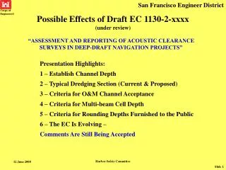
Harbor Safety Committee Possible Effects of Draft EC 1130-2-xxxx (under review) “ASSESSMENT AND REPORTING OF ACOUSTIC CLEARANCE SURVEYS IN DEEP-DRAFT NAVIGATION PROJECTS” Presentation Highlights: 1 – Establish Channel Depth 2 – Typical Dredging Section (Current & Proposed) 3 – Criteria for O&M Channel Acceptance 4 – Criteria for Multi-beam Cell Depth 5 – Criteria for Rounding Depths Furnished to the Public 6 – The EC Is Evolving – Comments Are Still Being Accepted
Harbor Safety Committee { Justification for advance maintenance should describe historical shoaling rates, frequency of dredging, and cost analysis. * Usually 0 ft 1 to 2 ft * How do you establish underkeel clearance? Establish Channel Depth 2 ft DREDGING TOLERANCE
Harbor Safety Committee Current Typical Dredging Section (O&M Dredging) Dredging Limitations: “Contour” Payment for In-Channel OD No Side-slope Dredging BUT Payment for material that sloughs off of side slope No Payment for Side-slope OD Dredging Tolerance: 1’ Allowable (Paid) OD 1’ Allowable (Non-Paid) OD
Harbor Safety Committee EC 1130-2-xxxx Typical Dredging Section (soft bottom maintenance dredging) New: Survey Uncertainty Tolerance Unclear Aspects (especially in the SF Bay area): Side-slope Dredging Side-slope Over Depth Non-pay Over Depth Total Volume of Dredged Material (Pay & Non-Pay)
Harbor Safety Committee Material falling within the survey uncertainty tolerance window need not be removed. Estimated Survey Tolerance * Allowable Over Depth *Since the statistical computations are complex, practical engineering judgment necessitates that an estimated "average survey tolerance" be assigned to specific surveys. Criteria for O&M Channel Acceptance Required Channel Depth The survey tolerance is defined as the estimated repeatability or reproducibility of the statistical average of multiple acoustic measurements made over a finite area or cell, and at a specific project site using the same or different measurement systems.
Harbor Safety Committee Criteria for Multi-beam Cell Depth Depths in a Cell Average Minimum EC 1130-2-xxxx specifies using Average Cell Depth (minimum depth in a cell shall never be used) San Francisco District Plans to Acquire Multi-beam Survey System in FY09
Harbor Safety Committee Better Equipment & Procedures Yields Smaller Survey Tolerance Estimated Survey Tolerance * * Nearest 0.5 ft is the highest “accuracy” that can be published. Allowable Over Depth ~ Published Soundings Required Channel Depth Criteria for Rounding Depths Furnished to the Public Survey Tolerance >0.5 ft => Round to Nearest 1.0 ft Survey Tolerance ±0.2 ft to ±0.5 ft => Round to Nearest 0.5 ft
Harbor Safety Committee Possible Effects of Draft EC 1130-2-xxxx (Summary) 1 – Criteria for Channel Acceptance A – Estimated Survey Tolerance (EST >= 0.2 ft) B – High Spots (<= EST) Are Acceptable 2 – Criteria for Multi-beam Cell Depth (use average depth) 3 – Criteria for Rounding Published Depths(± 0.5 ft or ± 1.0 ft) Taking Uncertainties into Account Recognizing the steep learning curves for all things new: 4 – First priority = reduce EST of Government surveys 5 – Next priority = improve survey posting timeline The Engineering Circular is evolving – Comments Are Still Being Accepted
Harbor Safety Committee Possible Effects of Draft EC 1130-2-xxxx (under review) “ASSESSMENT AND REPORTING OF ACOUSTIC CLEARANCE SURVEYS IN DEEP-DRAFT NAVIGATION PROJECTS” The End Final Version of EC 1130-2-xxxx – July 2008 QUESTIONS?
Harbor Safety Committee Corps of Engineers® Harbor Safety Committee Briefing(12 June 2008) San Francisco Engineer District STOP Back Up Slides Follow
Harbor Safety Committee Current Data Collection System DGPS for horizontal position Without Compensator Weakest Link Tide Elevations for vertical Heave-Pitch Compensator Suboptimal Performance
Harbor Safety Committee Error Budget Measurement System Accuracy Velocity Calibration Accuracy Sounder Resolution Draft/Index Accuracy Tide/Stage Correction Accuracy Platform Stability Error Vessel Velocity Error 0.1 ft Old Sounders in Deep Channels vs New in Shallow 0.1 ft Stationary Bar Checking vs Dynamic Surveying 0.1 ft 0.1 ft Precision ≠ 0.1 ft Accuracy 0.1 ft Constant “draft” Correction vs Loading Changes during the Survey 0.25 ft On-shore Reference Benchmark vs tidal surface gradient errors 0.3 ft Effects of sea Roll, Pitch, and Heave 0.1 ft Squat Test Conditions vs Operating Velocity and Loading Bottom Reflectivity/Sensitivity 0.1 ft Echo sounding returns are dependent on the frequency of the acoustic pulse, receiver sensitivity settings, and distinct density changes in the subsurface material. Inherent Survey Uncertainties No matter how repeatable our surveys are, we are still just estimating the channel depth. ± 0.9 ft = RMS (95%) Quantitative estimate of acoustic depth measurement accuracy
: 0.1 ft : 0.1 ft : 0.25 ft : 0.3 ft Error Budget New Positioning System POS MV 320 GPS-Aided Inertial Navigation System functionality of a GPS receiver, gyrocompass & conventional motion sensor BETTER: - Draft/Index Accuracy - Vessel Velocity Error - Tide/Stage Correction Accuracy - Platform Stability Error • POS (Position and Orientation System) Computer System • controls the IMU and GPS receivers • computes velocity, roll, pitch and true heading • outputs data in the correct format to interface with Hypack • Inertial Measurement Unit (IMU) • contains 3 gyroscopes and 3 accelerometers • GPS Sub-system • two antennas plus two receiver cards embedded in POS Computer • computes position to 0.02m with optional RTK Heave-Pitch-Roll Compensation Critical for Multibeam Horizontal & Vertical Position Position ± 0.07 foot Harbor Safety Committee
Harbor Safety Committee Standards and Specifications for Acoustic Surveys Contract Specifications Quantity Computation Procedures Selection of Controlling Depths Use of Multi-beam Survey Systems RTK Position and Elevation Control Response Times for Dissemination of Survey Data Other Aspects Covered (Draft EC 1130-2-xxxx) The devil is in the details!