Download

1 / 13
140 likes | 470 Vues
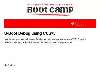
Debug TI Keystone II U-Boot with CCSv5. Vincent Han Mar, 2014. Agenda. Basic U-boot Code Structure Debug on TCI6638EVM with CCSv5. Basic Keystone II U-boot Code Structure. U-boot Relocation Mechanism. U-boot designs the HW initialization as 2 parts

E N D
Debug TI Keystone II U-Boot with CCSv5 Vincent Han Mar, 2014
Agenda • Basic U-boot Code Structure • Debug on TCI6638EVM with CCSv5
U-boot Relocation Mechanism • U-boot designs the HW initialization as 2 parts • 1st part is function “board_init_f” • 2nd part is function “board_init_r” • There will be sections’ relocation operation during these 2 steps • Benefits of this design: • Can implement on some platforms have little on-chip SRAM to run entire image (e.g. have little size of on-chip memory but have enough room on DDR) • Can improve the code execute efficiency (e.g. first run on Flash then relocate the code and run on SRAM) • Although Keystone II devices have enough on-chip SRAM ,the Keystone II U-boot code still keeps this mechanism
Agenda • Basic U-boot Code Structure • Debug on TCI6638EVM with CCSv5
Debug on TCI6638EVM with CCSv5 • Launch the debug session and connect the target • Please do not use any ARM core gel file • Connect with the 1st ARM core on TCI6638 (other 3 cores are power-off after reset) • Load symbol to the target • After you load the symbol table, some of the symbols/functions which defined in U-boot image can be recognized by CCS • Load bin file to the target • Choose the load address “0x0C00_1000” and choose the 32-bit load mode • Change PC and map code in CCS • Add PC pointer in expression view and force PC pointer point to “0x0C00_1000” • Step into/over in the disassembly view by clicking green buttons until the PC pointer point to “board_init_f”
Debug on TCI6638EVM with CCSv5 • Click “step into” to go to this function, you will see the following hints in code view window • Click “Locate File” to locate the correct path of board.c on your PC • Then you can debug the first part of hardware configurations code calling in function “board_init_f” • Get the relocate address from code • Function “board_init_f” will calculate the relocation address and store it in “id->relocaddr”, we can get this value in the end part of this function • Remap code in CCS for relocation • After the relocation, the disassembly pointer and source code pointer will not be match with each other, which need our manually adjust to correct offset • We need to run just before calling “relocate_code” in function “_main” by setting the hardware breakpoint
Debug on TCI6638EVM with CCSv5 • Then reload the symbol by adding the previous offset “0xBFF5_6000” to get the correct source code and disassembly pointer after the relocation for further debugging • The code and disassembly pointer will adjust to the correct place after relocation • We can switch to the correct address of “board_init_r” and make a hardware breakpoint in that place, then execute the code to stop at that breakpoint • We need to make the breakpoint at the adjusted address rather than the address before the relocation, or the breakpoint point to the different place and cannot stop correctly • We can see that after we stopped after relocation, the assembly code seemed incorrect due to the CCS disassembly view window parse the code in 32-bit ARM mode other than 16-bit Thumb mode, which needs us manually change the disassembly code view to Thumb mode • After this step, you can move on to debug the U-boot code in CCS by step into/over • For more information, please refer operation guide on deyisupport
Boot Linux Kernel (UBI File-system) • For the next boot procedure, if you configured the environment variables correctly, U-Boot will boot Linux Kernel automatically by default. • Using UBI file-system, Linux Kernel, Boot Monitor and DTB files will be burnt on NAND flash, Ethernet is not needed during every boot time.