Design of a Complex Vending Machine Logic
60 likes | 188 Vues
This document outlines the logic design of a complex vending machine utilizing coded inputs for coins (quarters, dimes, and nickels) and detailed state transitions. The machine can either accept or reject coin inputs, with mechanisms for returning coins or products based on state changes. An advanced multiplexer circuit is implemented to manage multiple inputs and outputs, utilizing select signals for functionality. The design highlights sequential state behavior, coin return logic, and product dispensing, emphasizing the utility of multiplexers in simplifying circuit design.

Design of a Complex Vending Machine Logic
E N D
Presentation Transcript
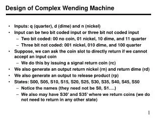
Design of Complex Wending Machine • Inputs: q (quarter), d (dime) and n (nickel) • Input can be two bit coded input or three bit not coded input • Two bit coded: 00 no coin, 01 nickel, 10 dime, and 11 quarter • Three bit not coded: 001 nickel, 010 dime, and 100 quarter • Suppose, we can ask the coin slot to directly return if we cannot accept an input coin • We do this by issuing a signal return coin (rc) • We also generate an output return nickel (rn) and return dime (rd) • We also generate an output to release product (rp) • States: S00, S05, S10, S15, S20, S25, S30, S35, S40, S45, S50 • Notice the names (they need not be S0, S1….) • We also may have S30’ and S35’ where we return coins (we do not need to return in any other state)
S35’ d n q q d d d d S05 S15 S25 S35 S45 q q q n n n n n S00 q d n q n n q S10 S20 S30 S40 S50 d d d q n d S30’ q State Changes in Wending Machine Outputs (rc, rn, rd, rp) = (0, 0, 0, 1) in S40 Outputs (rc, rn, rd, rp) = (0, 1, 0, 1) in S45 Outputs (rc, rn, rd, rp) = (0, 0, 1, 1) in S50 Outputs (rc, rn, rd, rp) = (0, 0, 0, 0) in S00, S05, S10, S15, S20, S25, S30, S35 Outputs (rc, rn, rd, rp) = (1, 0, 0, 0) in S30’ and S35’
I0 I1 I2 I3 I4 I5 I6 I7 X Y Z S2 S1 S0 0 1 2 3 4 5 6 7 F Multiplexing and Multiplexer • Multiplexers is a circuits which selects one of many inputs • First let us assume that we have one bit inputs • And we have eight inputs, I0, I1, I2, I3, I4, I5, I6, I7 • We want one of them to be output based on selection signal • We need a 3 bit select input to decide which input goes to output • Note the order of select signals • X is MSB and Z is LSB
I0 I1 I2 I3 I4 I5 I6 I7 X Y Z S2 S1 S0 0 1 2 3 4 5 6 7 F Multiplexer Design • We can write a logic equation for output F as follows F = X’ Y’ Z’ I0 + X’ Y’ Z I1 + X’ Y Z’ I2 + X’ Y Z I3 + X Y’ Z’ I5 + X Y’ Z I6 + X Y Z’ I6 + X Y Z I7 • This circuit can be implemented using • 8 four-input AND gates and one OR gates
S2 S1 S0 0 1 2 3 4 5 6 7 F Designing with multiplexers • Multiplexers can be directly used to implement as a circuit • Easiest way is to use function input as selection signals • Input to multiplxer is a set of 1s and 0s depending on the function to be implemented • We use a 8 to 1 multiplexer to implement function F • Three select signals are X, Y, and Z, and output is F • Eight inputs to multiplexer are 1 0 1 0 1 1 0 0 • Depending on the input signal • multiplexer will select proper output
0 1 2 3 S1 S0 F Using Multiplexers • Suppose we want to design a rotate circuit • Inputs are i3 i2 i1 i0 • Output is zero, one, two, or three bit rotated output • Rotation can be in left or in right direction • Four sets of outputs are • i3 i2 i1 i0 • i2 i1 i0 i3 • i1 i0 i3 i2 • i0 i3 i2 i1 • Input/Output relations ship is given in the table • We can implement this circuit using four 4 to 1 multiplexers