Basic Interconnects
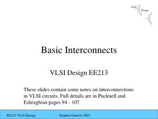
Basic Interconnects. VLSI Design EE213. These slides contain some notes on interconnections in VLSI circuits. Full details are in Pucknell and Eshraghian pages 94 - 107. Introduction. Wiring-Up of chip devices takes place through various conductors produced during processing

Basic Interconnects
E N D
Presentation Transcript
Basic Interconnects VLSI Design EE213 These slides contain some notes on interconnections in VLSI circuits. Full details are in Pucknell and Eshraghian pages 94 - 107
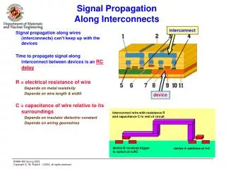
Introduction • Wiring-Up of chip devices takes place through various conductors produced during processing • Today, interconnects constitute the main source of delay in MOS circuits • We will examine: • Sheet Resistance – Resistance / Unit Area • Area Capacitance • Delay Units • CMOS Inverter Delay • Rise and Fall Time Estimation
Sheet Resistance A • Resistance of a square slab of material • RAB = ρL/A • => R = ρL/t*W • Let L = W (square slab) • => RAB = ρ/t = Rs ohm / square t w L B RAB = ZRsh Z = L/W
Typical sheet resistance values for materials are very well characterised Typical Sheet Resistances for 5µm Technology
N-type Minimum Feature Device Polysilicon L N - diffusion 2λ W 2λ R = 1sq x Rs = Rs = 104Ώ
Polysilicon W = 8λ L = 2λ N - diffusion R = Z Rs R = (L/W) * Rs R = 4 104Ώ
Exercise Calculate the ON resistance for a depletion pull – up Nmos inverter with Zpu : Zpd ratio 4:1 Use sheet resistance values given in earlier slide
Area Capacitance of Layers • Conducting layers are separated from each other by insulators (typically SiO2) • This may constitute a parallel plate capacitor, C = є0єox A / D (farads) • D = thickness of oxide, A = area, • єox = 4 F/µm2 • Area capacitance given in pF/µm2
Capacitance • Standard unit for a technology node is the gate - channel capacitance of the minimum sized transistor (2λ x 2λ), given as Cg • This is a ‘technology specific’ value
References • Pucknell and Eshraghian pages 94 - 102
Delay Unit • For a feature size square gate, τ = Rs x Cg • i.e for 5µm technology, τ = 104 ohm/sq x 0.01pF = 0.1ns • Because of effects of parasitics which we have not considered in our model, delay is typically of the order of 0.2 - 0.3 ns • Note that τ is very similar to channel transit time τsd
CMOS Inverter Delay • Pull-down delay = Rpd x 2 Cg • Pull-up delay = Rpu x 2Cg • Asymmetry in rise and fall due to resistance difference between pull-up and pull-down (factor of 2.5) (due to mobilities of carriers) • Delay through a pair of inverters is 2 τ (fall time) + 5 τ (rise time) • Delay through a pair of CMOS inverters is therefore 7 τ
CMOS Inverter Delay • Asymmetry can be improved by reducing resistance of pull - up • Reduce resistance of pull - up by increasing channel width ( typically by a factor of 2.5) • Note that increasing channel width also increases the capacitance • The overall delay (after increasing channel width by 2.5) will be the same 7 τ
CMOS Inverter Rise and Fall Time Estimation • Tf ~ 3CL / βVDD • Τr ~ 3CL / βVDD • (Derivations for the above are in Pucknell and Eshraghian Pages 105 - 107) • So, τ r/ τf = βn/βp • Given that (due to mobilities) βn = 2.5 βp, rise time is slower by a factor of 2.5 when using minimum dimensions of n and p transistors