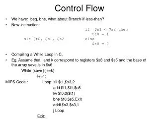
Flow Control and Error Control
Flow Control and Error Control. Shashank Srivastava Motilal Nehru national Institute Of Technology , Allahabad. FLOW AND ERROR CONTROL.

Flow Control and Error Control
E N D
Presentation Transcript
Flow Control and Error Control Shashank Srivastava Motilal Nehru national Institute Of Technology, Allahabad
FLOW AND ERROR CONTROL The most important responsibilities of the data link layer are flow control and error control. Collectively, these functions are known as data link control. Topics discussed in this section: Flow ControlError Control
Note Flow control refers to a set of procedures used to restrict the amount of data that the sender can send before waiting for acknowledgment.
Note Error control in the data link layer is based on automatic repeat request, which is the retransmission of data.
PROTOCOLS Now let us see how the data link layer can combine framing, flow control, and error control to achieve the delivery of data from one node to another. The protocols are normally implemented in software by using one of the common programming languages. To make our discussions language-free, we have written in pseudocode a version of each protocol that concentrates mostly on the procedure instead of delving into the details of language rules.
11-4 NOISELESS CHANNELS Let us first assume we have an ideal channel in which no frames are lost, duplicated, or corrupted. We introduce two protocols for this type of channel. Topics discussed in this section: Simplest ProtocolStop-and-Wait Protocol
Figure 11.6 The design of the simplest protocol with no flow or error control
Algorithm 11.1Sender-site algorithm for the simplest protocol
Algorithm 11.2Receiver-site algorithm for the simplest protocol
Example 11.1 Figure 11.7 shows an example of communication using this protocol. It is very simple. The sender sends a sequence of frames without even thinking about the receiver. To send three frames, three events occur at the sender site and three events at the receiver site. Note that the data frames are shown by tilted boxes; the height of the box defines the transmission time difference between the first bit and the last bit in the frame.
Algorithm 11.3Sender-site algorithm for Stop-and-Wait Protocol
Algorithm 11.4Receiver-site algorithm for Stop-and-Wait Protocol
Example 11.2 Figure 11.9 shows an example of communication using this protocol. It is still very simple. The sender sends one frame and waits for feedback from the receiver. When the ACK arrives, the sender sends the next frame. Note that sending two frames in the protocol involves the sender in four events and the receiver in two events.
11-5 NOISY CHANNELS Although the Stop-and-Wait Protocol gives us an idea of how to add flow control to its predecessor, noiseless channels are nonexistent. We discuss three protocols in this section that use error control. Topics discussed in this section: Stop-and-Wait Automatic Repeat RequestGo-Back-N Automatic Repeat RequestSelective Repeat Automatic Repeat Request
Note Error correction in Stop-and-Wait ARQ is done by keeping a copy of the sent frame and retransmitting of the frame when the timer expires.
Note In Stop-and-Wait ARQ, we use sequence numbers to number the frames. The sequence numbers are based on modulo-2 arithmetic.
Note In Stop-and-Wait ARQ, the acknowledgment number always announces in modulo-2 arithmetic the sequence number of the next frame expected.
Algorithm 11.5Sender-site algorithm for Stop-and-Wait ARQ (continued)
(continued) Algorithm 11.5Sender-site algorithm for Stop-and-Wait ARQ
Algorithm 11.6Receiver-site algorithm for Stop-and-Wait ARQ Protocol
Example 11.3 Figure 11.11 shows an example of Stop-and-Wait ARQ. Frame 0 is sent and acknowledged. Frame 1 is lost and resent after the time-out. The resent frame 1 is acknowledged and the timer stops. Frame 0 is sent and acknowledged, but the acknowledgment is lost. The sender has no idea if the frame or the acknowledgment is lost, so after the time-out, it resends frame 0, which is acknowledged.
Example 11.4 Assume that, in a Stop-and-Wait ARQ system, the bandwidth of the line is 1 Mbps, and 1 bit takes 20 ms to make a round trip. What is the bandwidth-delay product? If the system data frames are 1000 bits in length, what is the utilization percentage of the link? Solution The bandwidth-delay product is
Example 11.4 (continued) The system can send 20,000 bits during the time it takes for the data to go from the sender to the receiver and then back again. However, the system sends only 1000 bits. We can say that the link utilization is only 1000/20,000, or 5 percent. For this reason, for a link with a high bandwidth or long delay, the use of Stop-and-Wait ARQ wastes the capacity of the link.
Example 11.5 What is the utilization percentage of the link in Example 11.4 if we have a protocol that can send up to 15 frames before stopping and worrying about the acknowledgments? Solution The bandwidth-delay product is still 20,000 bits. The system can send up to 15 frames or 15,000 bits during a round trip. This means the utilization is 15,000/20,000, or 75 percent. Of course, if there are damaged frames, the utilization percentage is much less because frames have to be resent.
Note In the Go-Back-N Protocol, the sequence numbers are modulo 2m, where m is the size of the sequence number field in bits.
Note The send window is an abstract concept defining an imaginary box of size 2m − 1 with three variables: Sf, Sn, and Ssize.
Note The send window can slide oneor more slots when a valid acknowledgment arrives.
Note The receive window is an abstract concept defining an imaginary box of size 1 with one single variable Rn. The window slides when a correct frame has arrived; sliding occurs one slot at a time.
Note In Go-Back-N ARQ, the size of the send window must be less than 2m; the size of the receiver window is always 1.
Algorithm 11.7Go-Back-N sender algorithm (continued)
(continued) Algorithm 11.7Go-Back-N sender algorithm
Example 11.6 Figure 11.16 shows an example of Go-Back-N. This is an example of a case where the forward channel is reliable, but the reverse is not. No data frames are lost, but some ACKs are delayed and one is lost. The example also shows how cumulative acknowledgments can help if acknowledgments are delayed or lost. After initialization, there are seven sender events. Request events are triggered by data from the network layer; arrival events are triggered by acknowledgments from the physical layer. There is no time-out event here because all outstanding frames are acknowledged before the timer expires. Note that although ACK 2 is lost, ACK 3 serves as both ACK 2 and ACK 3.
Example 11.7 Figure 11.17 shows what happens when a frame is lost. Frames 0, 1, 2, and 3 are sent. However, frame 1 is lost. The receiver receives frames 2 and 3, but they are discarded because they are received out of order. The sender receives no acknowledgment about frames 1, 2, or 3. Its timer finally expires. The sender sends all outstanding frames (1, 2, and 3) because it does not know what is wrong. Note that the resending of frames 1, 2, and 3 is the response to one single event. When the sender is responding to this event, it cannot accept the triggering of other events. This means that when ACK 2 arrives, the sender is still busy with sending frame 3.
Example 11.7 (continued) The physical layer must wait until this event is completed and the data link layer goes back to its sleeping state. We have shown a vertical line to indicate the delay. It is the same story with ACK 3; but when ACK 3 arrives, the sender is busy responding to ACK 2. It happens again when ACK 4 arrives. Note that before the second timer expires, all outstanding frames have been sent and the timer is stopped.
Note Stop-and-Wait ARQ is a special case of Go-Back-N ARQ in which the size of the send window is 1.