Microwave Devices
Microwave Devices. Introduction. Microwaves have frequencies > 1 GHz approx. Stray reactances are more important as frequency increases Transmission line techniques must be applied to short conductors like circuit board traces Device capacitance and transit time are important

Microwave Devices
E N D
Presentation Transcript
Introduction • Microwaves have frequencies > 1 GHz approx. • Stray reactances are more important as frequency increases • Transmission line techniques must be applied to short conductors like circuit board traces • Device capacitance and transit time are important • Cable losses increase: waveguides often used instead
Waveguides • Pipe through which waves propagate • Can have various cross sections • Rectangular • Circular • Elliptical • Can be rigid or flexible • Waveguides have very low loss
Modes • Waves can propagate in various ways • Time taken to move down the guide varies with the mode • Each mode has a cutoff frequency below which it won’t propagate • Mode with lowest cutoff frequency is dominant mode
Mode Designations • TE: transverse electric • Electric field is at right angles to direction of travel • TM: transverse magnetic • Magnetic field is at right angles to direction of travel • TEM: transverse electromagnetic • Waves in free space are TEM
Rectangular Waveguides • Dominant mode is TE10 • 1 half cycle along long dimension (a) • No half cycles along short dimension (b) • Cutoff for a = c/2 • Modes with next higher cutoff frequency are TE01 and TE20 • Both have cutoff frequency twice that for TE10
Cutoff Frequency • For TE10 mmode in rectangular waveguide with a = 2 b
Usable Frequency Range • Single mode propagation is highly desirable to reduce dispersion • This occurs between cutoff frequency for TE10 mode and twice that frequency • It’s not good to use guide at the extremes of this range
Example Waveguide • RG-52/U • Internal dimensions 22.9 by 10.2 mm • Cutoff at 6.56 GHz • Use from 8.2-12.5 GHz
Group Velocity • Waves propagate at speed of light c in guide • Waves don’t travel straight down guide • Speed at which signal moves down guide is the group velocity and is always less than c
Phase Velocity • Not a real velocity (>c) • Apparent velocity of wave along wall • Used for calculating wavelength in guide • For impedance matching etc.
Characteristic Impedance • Z0 varies with frequency
Guide Wavelength • Longer than free-space wavelength at same frequency
Impedance Matching • Same techniques as for coax can be used • Tuning screw can add capacitance or inductance
Coupling Power to Guides • 3 common methods • Probe: at an E-field maximum • Loop: at an H-field maximum • Hole: at an E-field maximum
Directional Coupler • Launches or receives power in only 1 direction • Used to split some of power into a second guide • Can use probes or holes
Passive Compenents • Bends • Called E-plane or H-Plane bends depending on the direction of bending • Tees • Also have E and H-plane varieties • Hybrid or magic tee combines both and can be used for isolation
Resonant Cavity • Use instead of a tuned circuit • Very high Q
Attenuators and Loads • Attenuator works by putting carbon vane or flap into the waveguide • Currents induced in the carbon cause loss • Load is similar but at end of guide
Circulator and Isolator • Both use the unique properties of ferrites in a magnetic field • Isolator passes signals in one direction, attenuates in the other • Circulator passes input from each port to the next around the circle, not to any other port
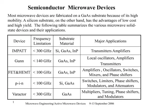
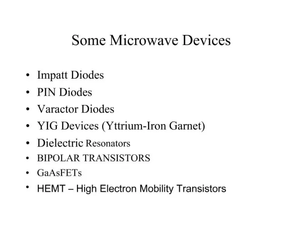
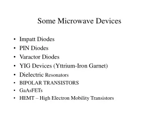
Microwave Transistors • Designed to minimize capacitances and transit time • NPN bipolar and N channel FETs preferred because free electrons move faster than holes • Gallium Arsenide has greater electron mobility than silicon
Gunn Device • Slab of N-type GaAs (gallium arsenide) • Sometimes called Gunn diode but has no junctions • Has a negative-resistance region where drift velocity decreases with increased voltage • This causes a concentration of free electrons called a domain
Transit-time Mode • Domains move through the GaAs till they reach the positive terminal • When domain reaches positive terminal it disappears and a new domain forms • Pulse of current flows when domain disappears • Period of pulses = transit time in device
Gunn Oscillator Frequency • T=d/v T = period of oscillation d = thickness of device v = drift velocity, about 1 105 m/s • f = 1/T
IMPATT Diode • IMPATT stands for Impact Avalanche And Transit Time • Operates in reverse-breakdown (avalanche) region • Applied voltage causes momentary breakdown once per cycle • This starts a pulse of current moving through the device • Frequency depends on device thickness
PIN Diode • P-type --- Intrinsic --- N-type • Used as switch and attenuator • Reverse biased - off • Forward biased - partly on to on depending on the bias
Varactor Diode • Lower frequencies: used as voltage-variable capacitor • Microwaves: used as frequency multiplier • this takes advantage of the nonlinear V-I curve of diodes
YIG Devices • YIG stands for Yttrium - Iron - Garnet • YIG is a ferrite • YIG sphere in a dc magnetic field is used as resonant cavity • Changing the magnetic field strength changes the resonant frequency
Dielectric Resonator • resonant cavity made from a slab of a dielectric such as alumina • Makes a good low-cost fixed-frequency resonant circuit
Microwave Tubes • Used for high power/high frequency combination • Tubes generate and amplify high levels of microwave power more cheaply than solid state devices • Conventional tubes can be modified for low capacitance but specialized microwave tubes are also used