Microwave Solid State Power Devices Yonglai Tian
670 likes | 987 Vues
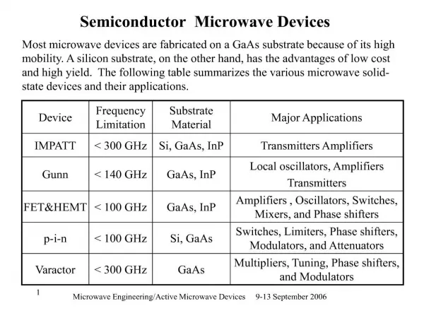
Microwave Solid State Power Devices Yonglai Tian. Introduction of microwave power devices Performance of Si and GaAs microwave devices Wide bandgap semiconductors for microwave applications Processing of WBG silicon carbide wafers SiC microwave power devices GaN microwave power device.

Microwave Solid State Power Devices Yonglai Tian
E N D
Presentation Transcript
Introduction of microwave power devices • Performance of Si and GaAs microwave devices • Wide bandgap semiconductors for microwave applications • Processing of WBG silicon carbide wafers • SiC microwave power devices • GaN microwave power device
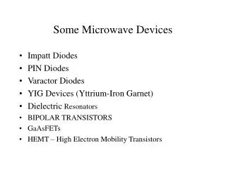
Various types of microwave power devices Magnetron Traveling wave tube Gyrotrons Klystron
Disadvantages • Large size • Heavy • Fixed frequency • Complicated power supply (HV) • Poor quality of waveform spectrum • Slow tuning and coupling • Cost Single mode cavity for Microwave sintering of advanced ceramics
Multiple DoD platform will benefit from microwave solid state devices and WBG semiconductors
Electrodeless HID lamps driven by microwaves 200w aperture HID lamps (7mm) driven by solid state microwave devices 1400wmagnetron driven HID lamps,
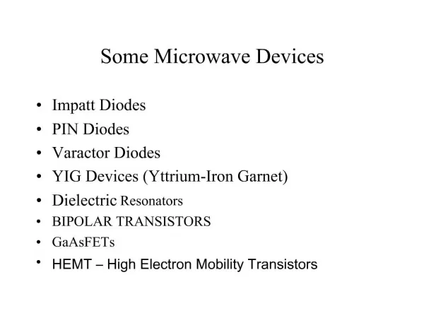
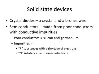
Various types of microwave solid state devices • Bipolar Junction Transistors (BJT) • Si BJT • HBT (hetero junction bipolar transistor) • AlGaAs-GaAs HBT • SiGe-Si HBT • Field Effect Transistors • GaAs MESFET (metal-semiconductor field effect transistors) • HEMT (high electron mobility transistors)
Various types of microwave solid state devices • Wide Bandgap Transistors • SiC • SIT (static induction transistors) • MESFET (metal-semiconductor field effect transistors) • HBT (hetero junction bipolar transistor) • GaN • HEMT (high electron mobility transistors)
Introduction of microwave power devices • Performance of Si and GaAs microwave devices • Wide bandgap semiconductors for microwave applications • Processing of WBG silicon carbide wafers • SiC microwave power devices • GaN microwave power device
Performance characterization • Out put power Pmax Pmax a Vmax x Imax • Vmax: Voltage breakdown • Imax: Heat removed, gate width and length • Power Density PD PD = Vmax x Current density • Vmax: Voltage breakdown • Current density: limited by bandgap and thermal conductivity
Performance characterization • Frequency f maxa (Vs/L) • Vs. saturated carrier velocity • Gate length Pmaα 1/f2 • Efficiency PAE Depends on wave shape, impedance, leakage current and power gain
Si BJT < 5 GHz 100-600W at 1 GHz > 40% Efficiency Low cost Limitation: Pmax: voltage breakdown and current (limited by emitter periphery and resistivity of epitaxial layer) f : limited by carrier mobility, capacitance C bc A typical Si BJT characteristics Frequency; 2.7-2.9 GHz Output power: 105 W Pulse width: 50 mm Duty cycle: 10% Gain: 6.5 db (min) Efficiency: 40% (min) Supply voltage: 40V Widely used Si microwave devices
GaAs MESFET (Metal semiconductor field effect transistors) • GaAs MSFET • 3-30 GHz • Power density: 0.5-0.8 w/mm • Power level and cost: Frequency band Power (W) cost ($) C and S 10 300 20 600 30 900 Ku 10 1000 15 1500 • Limitation: • f and Pmax: gate length, thermal conductivity
HEMT and HBT HEMT (High electronic mobility transistor) • AlGaAs-GaAs heterojunction • 5-100 GHz • High frequency • High Pmax • High efficiency • Low noise HBT (heterojunction bipolar junction transistor) • Similar to BJT, but much higher power and frequency performance
Introduction of microwave power devices • Performance of Si and GaAs microwave devices • Wide bandgap semiconductors for microwave applications • Processing of WBG silicon carbide wafers • SiC microwave power devices • GaN microwave power device
Advantages of wide bandgap semiconductors(SiC, GaN and diamond) • Wide bandgap • SiC: 3.2 eV • GaN: 3.4 eV • Si : 1.1 eV • GaAs: 1.4 eV 3 times higher than that of Si and GaAs • High service temperature of 650 oC due to the high intrinsic temperature • Low noise
Advantages • High breakdown voltage • SiC: 10 times higher than that of Si and GaAs • High output power due to high V • High operating frequency • Short-channel MESFETs in SiC Fmax : 50 GHz
Advantages 3. High thermal conductivity • SiC 4.9 w/(C-cm) 10 times higher than that of Si and GaAs • Si: 1.6 w/(C-cm) • GaN 0.5 w/(C-cm) • High Saturated velocity • SiC 2.2 x10⁷ m/s 2 times higher than that of Si and GaAs • Si and GaAs: 1 x10⁷ m/s
Physical characteristics of Si, GaAs and main wide bandgap semiconductors
Introduction of microwave power devices • Performance of Si and GaAs microwave devices • Wide bandgap semiconductors for microwave applications • Processing of WBG silicon carbide wafers • SiC microwave power devices • GaN microwave power device
Growth of SiC single crystal • J. A. Lely , Philips Labs 1955 sublimation process for growing a-SiC crystals • Davis at North Carolina State University (NCSU), 1987 seeded-growth sublimation process • Cree Res, started in 1987 by students from the NCSU. • Cree, 1990, Introduction of 25 mm single crystal wafers of 6H-SiC 1990
Physical vapor transport (PVT) growth of SiC single crystal wafers • PVT growth process: • Evaporation of SiC charge materials • Transport of vapor spices to the growth surface • Adsorption surface diffusion and incorporation of atoms into crystal. • Temperature: 2000-2300oC • DT of 10-30C controlled by moving RF coil • Growth rate controlled by DT and pressure in reactor
Defects in SiC wafer • Micropipes– breakdown at low voltage • Dislocations • Low angle grain boundaries • Stacking faults
GMU WBGS research projects:Ion implantation of SiC wafers • Ion implantation is the only viable selective area doping techniques for SiC device production • N and P were implanted in p-type and Al and B were implanted in n-type 6H-SiC using single and multiple ion energy schedules ranged from 50 KeV to 4 MeV • Second ion mass spectrometry measurements (SIMS) were conducted to obtain the implant depth profiles • Doping layer theickness.
Rapid annealing of ion implanted SiC • The crystal lattice is damaged by the penetration of ion energetic ions • Post annealing is necessary to recover the lattice damage • Microwave and conventional annealing at 1500C • Microwave: Heating rate; 200oC/min, total time: 20 min. • Conventional: heating rate: 10oC/min, total time 3 hr. • Rutherford backscattering (RBS) measurements are conducted before and after ion-implantation to study the recovery of the crystal lattice.
Sheet resistivity of nitrogen-implanted 4H-SiC as a function of time and temperature. Sheet resistivity of phosphorus-implanted 4H-SiC as a function of time and temperature.
Best Reported Sheet Resistivity of Ion Implanted SiC . Figure 2. Sheet resistivity of Al implants into 6H silicon carbide at room tmperature Figure 1. Sheet resistivity of nitrogen implants into 6H silicon carbide at room tmperature
Introduction of microwave power devices • Performance of Si and GaAs microwave devices • Wide bandgap semiconductors for microwave applications • Processing of WBG silicon carbide wafers • SiC microwave power devices • GaN microwave power device
SiC microwave power devices High power 4H-SiC static induction transistors (SITs) • Vertical short channel FET structure • Current flow vertically by modulating the internal potential of the channel using surrounding gate structure • Characteristics similar to a vacuum-tube tiode • 470W (1.36 /mm) at 600 MHz • 38 W (1.2 w/mm) at 3 GHz • PAE ~ 47%
High power 4H-SiC static induction transistors (SITs) Cross section of a SiC SIT SEM photo of a SIT device. The mesa fingers are 1 µm wide and 100 µm long. The total mesa length is 1 cm (100 fingers). Measured static I-V characteristics of a SIT
The best performance High output power; 900 W (at 1.3 GHz, drain efficiency = 65%, gain = 11 dB) [Northrop-Grumman/ Cree Inc] High frequency performance with a cut-off frequency of 7 GHz [Purdue] A comparison of SIT with other relevant SiC microwave devices..
High power SiC MESFET • Three epitaxial layers • P buffer layer • Channel layer doped Nd=3x1017cm-3 • Heavily doped n+ cap layer • Performance • Pmax : 15W • Frequency: 2.1 Ghz • Power density: 1w/mm • PAE; 54% a