Rotary Encoder
Robotics Club ,IIT Kanpur. Rotary Encoder. Wikipedia- Definition. A rotary encoder , also called a shaft encoder , is an electro-mechanical device that converts the angular position or motion of a shaft or axle to an analog or digital code. Types of Rotary encoders.


Rotary Encoder
E N D
Presentation Transcript
Robotics Club ,IIT Kanpur Rotary Encoder
Wikipedia- Definition • A rotary encoder, also called a shaft encoder, is an electro-mechanical device that converts the angular position or motion of a shaft or axle to an analog or digital code.
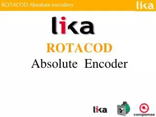
Absolute Type Rotary Encoder The absolute type of rotary encoder giver the absolute position of the shaft. For example – If the shaft has an absolute angle of 54(degrees) and it is 3 bit encoder. 3 bit encoder means it has 2^(3) divisions, therefore it will give value that the angle is more then 45 and less then 90. How to use this encoder- Just calculate the angle difference and counts of full rotation.This encoder will can be used in devices which has slow rotation speed and high accuracy.
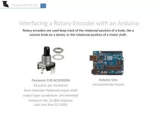
Incremental Type Encoders • An incremental rotary encoder provides cyclical outputs (only) when the encoder is rotated. • They employ two outputs called A & B which are called quadrature outputs as they are 90 degrees out of phase. • There can be an optional third output: reference, which happens once every turn. Two square waves in quadrature (clockwise rotation).
Incremental Rotary encoder • How to find the Speed of rotation ? • Ans- • Each encoder has some fixed number of slots per revolution. • Each slots generate one pulse. • If we count the number of pulses and time taken by the fixed number of pulses , we can calculate the speed of rotation of the shaft.
Applications • For odometery of mobile robot. • For precise measuring of the rotation of any shaft/rotation . • Linear encoder are also available which can be used for the linear distance moved
Magnetic encoder • Strips of magnetized material are placed on the rotating disc and are sensed by a Hall-Effect sensor or Magneto resistive sensor. Hall effect sensors are also used to sense gear-teeth directly, without the need for a separate encoder disc.
Optical Flow Sensor An optical flow sensor is a vision sensor capable of measuring optical flow or visual motion and outputting a measurement based on optical flow.
Applications • Optical mouse • Can act as vision for mobile robots. • Unmanned Ariel Vehicle (UAV’s)
ADNS 3080 Optical Flow sensor • ADNS-3080 optical sensor. • High speed motion detection. • Up to 6400 fps update rate. • 30x30 pixel resolution. • Includes an 8mm lens which can be replaced, depending on the use requirements
Features of Color sensor • Four channel integrated light to digital converter(Red, Green, Blue and Clear). • 10 bit per channel resolution • Independent gain selection for each channel • Wide sensitivity: 0.1k - 100k lux • Two wire serial communication • Built in oscillator/selectable external clock
Reflective color sensing By definition of reflective sensing, the color sensor detects light reflected from a surface or an object. The sensor module is designed in such a way that both the light source and the color sensor are placed closed to the target surface/object. Light coming from the LED is bounced off a surface/object and measured by the sensor.
White Calibration Before the color sensor can be used for reflective sensing, a one-time white calibration is needed to be done to set the sensor gain to the optimum setting. The white calibration is important to ensure minimal variation between different sensor unit and different LED unit. A white surface is illuminated by LED and detected by sensor with recommended working distance and the microcontroller/tester will perform the calibration.
Working • A laser rangefinder is a device which uses a laser beam to determine the distance to an object. The most common form of laser rangefinder operates on the time of flight principle by sending a laser pulse in a narrow beam towards the object and measuring the time taken by the pulse to be reflected off the target and returned to the sender
Parallax laser range finder • Compact module with integrated CMOS camera and laser system • Optimal measurement range of 6–48 inches (15–122 cm) with an accuracy error <5%, average 3% • Maximum object detection distance of ~8 feet (2.4 meters) • Range finding sample rate of 1Hz • Single row, 4-pin, 0.1” header for easy connection to a host system
Proximity Sensor • Easy to use digital obstacle detecting sensor • Easy calibration and very accurate